Picking up where I left off
by Bob Hunt
robinhunt@rcn.com
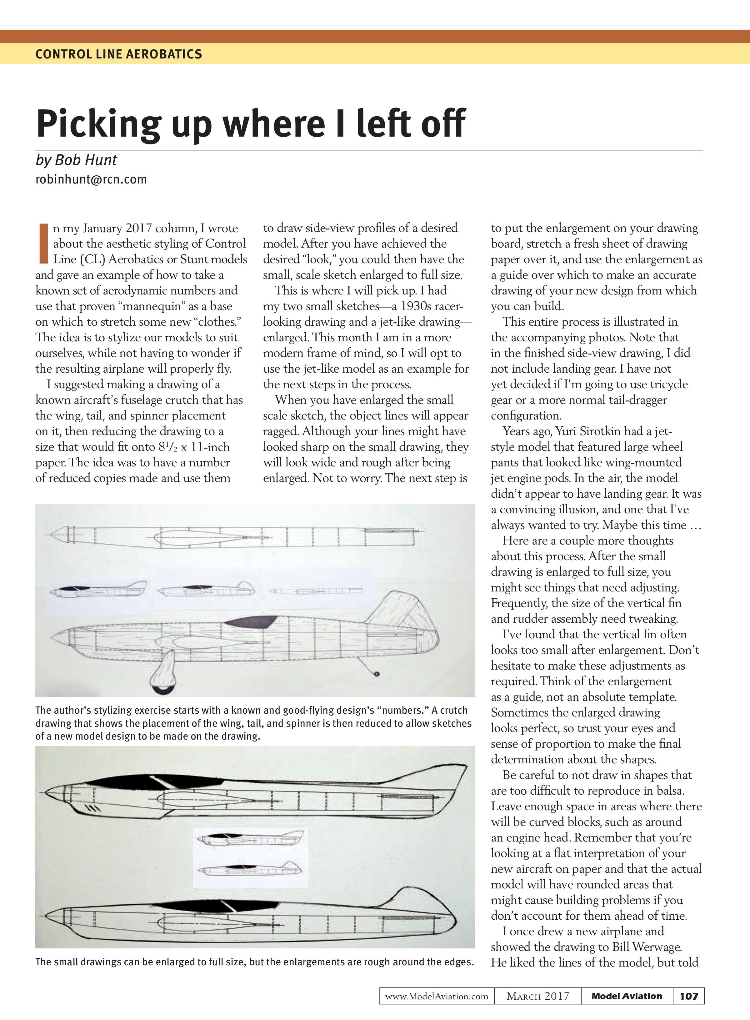
In my January 2017 column, I wrote about the aesthetic styling of Control Line (CL) Aerobatics or Stunt models and gave an example of how to take a known set of aerodynamic numbers and use that proven “mannequin” as a base on which to stretch some new “clothes.” The idea is to stylize our models to suit ourselves, while not having to wonder if the resulting airplane will properly fly.
I suggested making a drawing of a known aircraft’s fuselage crutch that has the wing, tail, and spinner placement on it, then reducing the drawing to a size that would fit onto 8½ x 11-inch paper. The idea was to have a number of reduced copies made and use them to draw side-view profiles of a desired model. After you have achieved the desired “look,” you could then have the small, scale sketch enlarged to full size.
This is where I will pick up. I had my two small sketches—a 1930s racer-looking drawing and a jet-like drawing—enlarged. This month I am in a more modern frame of mind, so I will opt to use the jet-like model as an example for the next steps in the process.
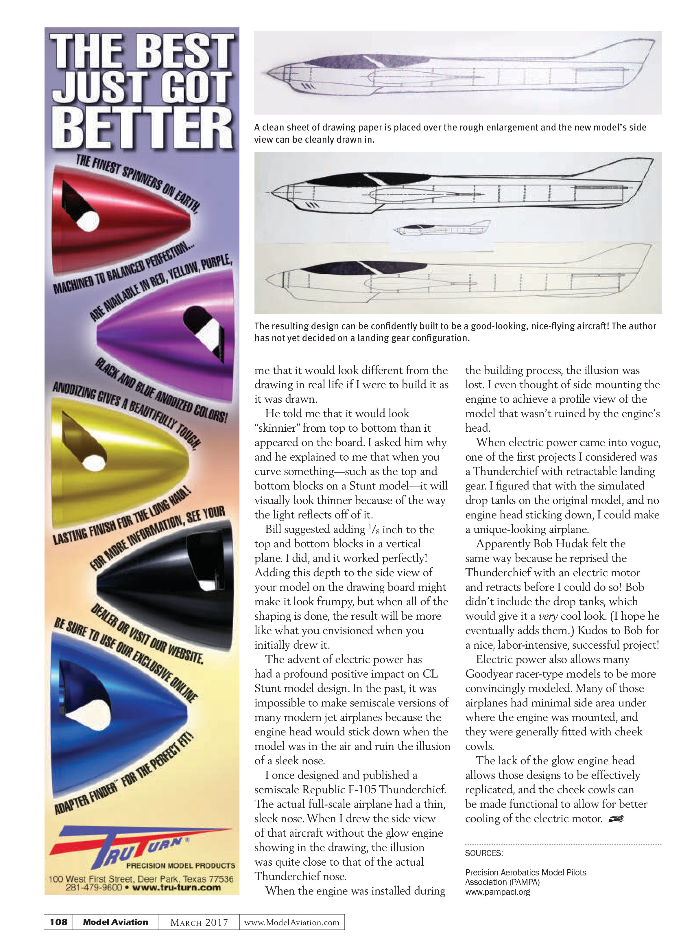
When you have enlarged the small scale sketch, the object lines will appear ragged. Although your lines might have looked sharp on the small drawing, they will look wide and rough after being enlarged. Not to worry. The next step is

to put the enlargement on your drawing board, stretch a fresh sheet of drawing paper over it, and use the enlargement as a guide over which to make an accurate drawing of your new design from which you can build.
This entire process is illustrated in the accompanying photos. Note that in the finished side-view drawing, I did not include landing gear. I have not yet decided if I’m going to use tricycle gear or a more normal tail-dragger configuration.
Years ago, Yuri Sirotkin had a jet-style model that featured large wheel pants that looked like wing-mounted jet engine pods. In the air, the model didn’t appear to have landing gear. It was a convincing illusion, and one that I’ve always wanted to try. Maybe this time …
Here are a couple more thoughts about this process. After the small drawing is enlarged to full size, you might see things that need adjusting. Frequently, the size of the vertical fin and rudder assembly need tweaking.
I’ve found that the vertical fin often looks too small after enlargement. Don’t hesitate to make these adjustments as required. Think of the enlargement as a guide, not an absolute template. Sometimes the enlarged drawing looks perfect, so trust your eyes and sense of proportion to make the final determination about the shapes.
Be careful to not draw in shapes that are too difficult to reproduce in balsa. Leave enough space in areas where there will be curved blocks, such as around an engine head. Remember that you’re looking at a flat interpretation of your new aircraft on paper and that the actual model will have rounded areas that might cause building problems if you don’t account for them ahead of time.
I once drew a new airplane and showed the drawing to Bill Werwage. He liked the lines of the model, but told

me that it would look different from the drawing in real life if I were to build it as it was drawn.
He told me that it would look “skinnier” from top to bottom than it appeared on the board. I asked him why and he explained to me that when you curve something—such as the top and bottom blocks on a Stunt model—it will visually look thinner because of the way the light reflects off of it.
Bill suggested adding ⅛ inch to the top and bottom blocks in a vertical plane. I did, and it worked perfectly! Adding this depth to the side view of your model on the drawing board might make it look frumpy, but when all of the shaping is done, the result will be more like what you envisioned when you initially drew it.
The advent of electric power has had a profound positive impact on CL Stunt model design. In the past, it was impossible to make semiscale versions of many modern jet airplanes because the engine head would stick down when the model was in the air and ruin the illusion of a sleek nose.
I once designed and published a semiscale Republic F-105 Thunderchief. The actual full-scale airplane had a thin, sleek nose. When I drew the side view of that aircraft without the glow engine showing in the drawing, the illusion was quite close to that of the actual Thunderchief nose.
When the engine was installed during the building process, the illusion was lost. I even thought of side mounting the engine to achieve a profile view of the model that wasn’t ruined by the engine’s head.
When electric power came into vogue, one of the first projects I considered was a Thunderchief with retractable landing gear. I figured that with the simulated drop tanks on the original model, and no engine head sticking down, I could make a unique-looking airplane.
Apparently Bob Hudak felt the same way because he reprised the Thunderchief with an electric motor and retracts before I could do so! Bob didn’t include the drop tanks, which would give it a very cool look. (I hope he eventually adds them.) Kudos to Bob for a nice, labor-intensive, successful project!
Electric power also allows many Goodyear racer-type models to be more convincingly modeled. Many of those airplanes had minimal side area under where the engine was mounted, and they were generally fitted with cheek cowls.
The lack of the glow engine head allows those designs to be effectively replicated, and the cheek cowls can be made functional to allow for better cooling of the electric motor.


SOURCES:
Precision Aerobatics Model Pilots Association (PAMPA)
www.pampacl.org