Rolling turns and Humpty Bumps
by John Glezellis
jglezellis@gmail.com

Becoming a successful International Miniature Aerobatic Club (IMAC) competition pilot requires you to have the ability to read and interpret the Aresti diagram, which is the language of aerobatics. Aresti diagrams can be confusing for newcomers and experienced pilots alike. For beginners, it takes time and exposure to become familiar with each element that contributes to an individual maneuver, whereas experienced pilots might overlook specific components of a figure and mistake one element for another.
The 2017 schedules were recently released, so this month I will take a look at two maneuvers from the official 2017 Scale Aerobatics Advanced Known program. I will not only examine the different individual Aresti elements and judging criteria, but also discuss a few control input and planning techniques to perform these figures to perfection. Without further hesitation, let’s begin!
Rolling Turns and Humpty Bumps
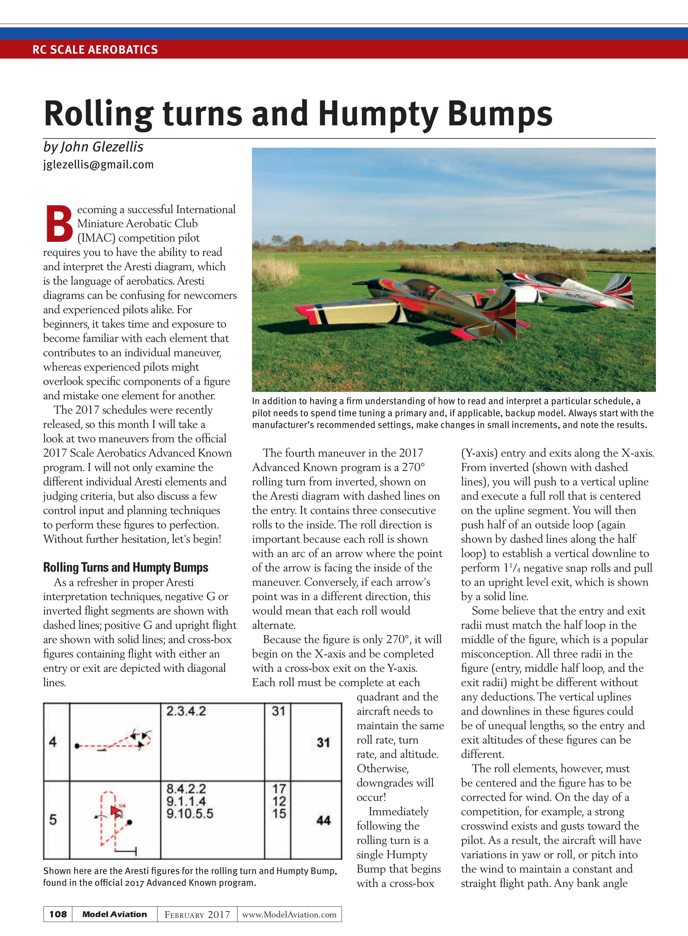
As a refresher in proper Aresti interpretation techniques, negative G or inverted flight segments are shown with dashed lines; positive G and upright flight are shown with solid lines; and cross-box figures containing flight with either an entry or exit are depicted with diagonal lines.

The fourth maneuver in the 2017 Advanced Known program is a 270° rolling turn from inverted, shown on the Aresti diagram with dashed lines on the entry. It contains three consecutive rolls to the inside. The roll direction is important because each roll is shown with an arc of an arrow where the point of the arrow is facing the inside of the maneuver. Conversely, if each arrow’s point was in a different direction, this would mean that each roll would alternate.
Because the figure is only 270°, it will begin on the X-axis and be completed with a cross-box exit on the Y-axis. Each roll must be complete at each quadrant and the aircraft needs to maintain the same roll rate, turn rate, and altitude. Otherwise, downgrades will occur!
Immediately following the rolling turn is a single Humpty Bump that begins with a cross-box (Y-axis) entry and exits along the X-axis. From inverted (shown with dashed lines), you will push to a vertical upline and execute a full roll that is centered on the upline segment. You will then push half of an outside loop (again shown by dashed lines along the half loop) to establish a vertical downline to perform 1¼ negative snap rolls and pull to an upright level exit, which is shown by a solid line.
Some believe that the entry and exit radii must match the half loop in the middle of the figure, which is a popular misconception. All three radii in the figure (entry, middle half loop, and the exit radii) might be different without any deductions. The vertical uplines and downlines in these figures could be of unequal lengths, so the entry and exit altitudes of these figures can be different.
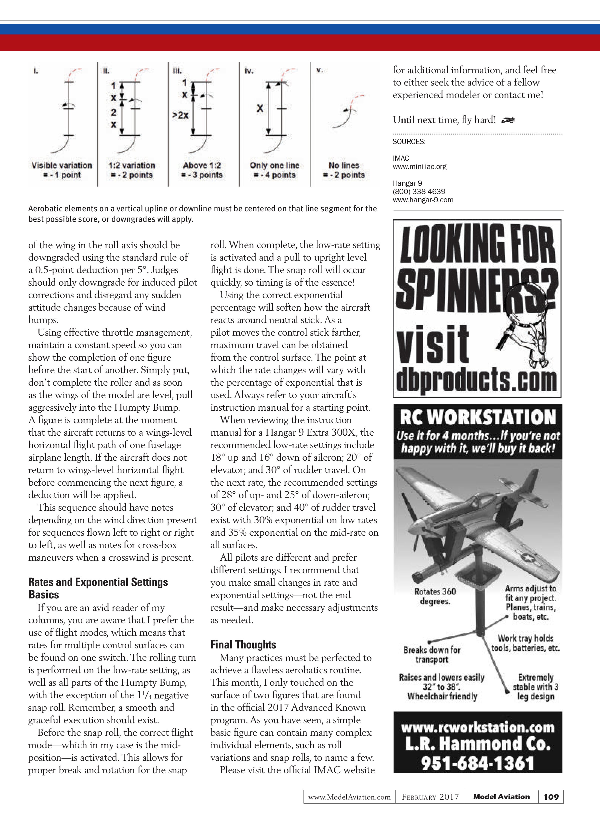
The roll elements, however, must be centered and the figure has to be corrected for wind. On the day of a competition, for example, a strong crosswind exists and gusts toward the pilot. As a result, the aircraft will have variations in yaw or roll, or pitch into the wind to maintain a constant and straight flight path. Any bank angle of the wing in the roll axis should be downgraded using the standard rule of a 0.5-point deduction per 5°. Judges should only downgrade for induced pilot corrections and disregard any sudden attitude changes because of wind bumps.
Using effective throttle management, maintain a constant speed so you can show the completion of one figure before the start of another. Simply put, don’t complete the roller and as soon as the wings of the model are level, pull aggressively into the Humpty Bump. A figure is complete at the moment that the aircraft returns to a wings-level horizontal flight path of one fuselage airplane length. If the aircraft does not return to wings-level horizontal flight before commencing the next figure, a deduction will be applied.
This sequence should have notes depending on the wind direction present for sequences flown left to right or right to left, as well as notes for cross-box maneuvers when a crosswind is present.
Rates and Exponential Settings Basics
If you are an avid reader of my columns, you are aware that I prefer the use of flight modes, which means that rates for multiple control surfaces can be found on one switch. The rolling turn is performed on the low-rate setting, as well as all parts of the Humpty Bump, with the exception of the 1¼ negative snap roll. Remember, a smooth and graceful execution should exist.
Before the snap roll, the correct flight mode—which in my case is the mid-position—is activated. This allows for proper break and rotation for the snap roll. When complete, the low-rate setting is activated and a pull to upright level flight is done. The snap roll will occur quickly, so timing is of the essence!
Using the correct exponential percentage will soften how the aircraft reacts around neutral stick. As a pilot moves the control stick farther, maximum travel can be obtained from the control surface. The point at which the rate changes will vary with the percentage of exponential that is used. Always refer to your aircraft’s instruction manual for a starting point.
When reviewing the instruction manual for a Hangar 9 Extra 300X, the recommended low-rate settings include 18° up and 16° down of aileron; 20° of elevator; and 30° of rudder travel. On the next rate, the recommended settings of 28° of up- and 25° of down-aileron; 30° of elevator; and 40° of rudder travel exist with 30% exponential on low rates and 35% exponential on the mid-rate on all surfaces.
All pilots are different and prefer different settings. I recommend that you make small changes in rate and exponential settings—not the end result—and make necessary adjustments as needed.
Final Thoughts
Many practices must be perfected to achieve a flawless aerobatics routine. This month, I only touched on the surface of two figures that are found in the official 2017 Advanced Known program. As you have seen, a simple basic figure can contain many complex individual elements, such as roll variations and snap rolls, to name a few.
Please visit the official IMAC website for additional information, and feel free to either seek the advice of a fellow experienced modeler or contact me!
Until next time, fly hard!

Aerobatic elements on a vertical upline or downline must be centered on that line segment for the best possible score, or downgrades will apply.
SOURCES:
IMAC
www.mini-iac.org
Hangar 9
(800) 338-4639
www.hangar-9.com