A multipurpose CL model for Profile Scale or Navy Carrier


Bill Darkow discovered the Curtiss XF7C-3 Seahawk in the November 1935 Model Airplane News, which showed a Wylam three-view with a notation that “plans, photographs, and information on this model are unobtainable.” A Wylam drawing of an F7C-1 Seahawk in the December 1963 Model Airplane News supplied that information, stating that the XF7C-3 was a U.S. Navy and export markets project built under wraps.
On its maiden flight, the aircraft caught fire and was destroyed, killing the pilot, which ended any further development of that Seahawk series.
Two XF7C-3 prototype models were tested and flown for Bill’s article; John Hall completed his in time to compete in the Pacific Northwest Regional Control Line (CL) Championships in Oregon. It didn’t win, but it attracted a lot of attention. Bill and John differed in thoughts about their builds, but they both favored the simplicity of the construction and took care not to compromise any of the scale accuracy.
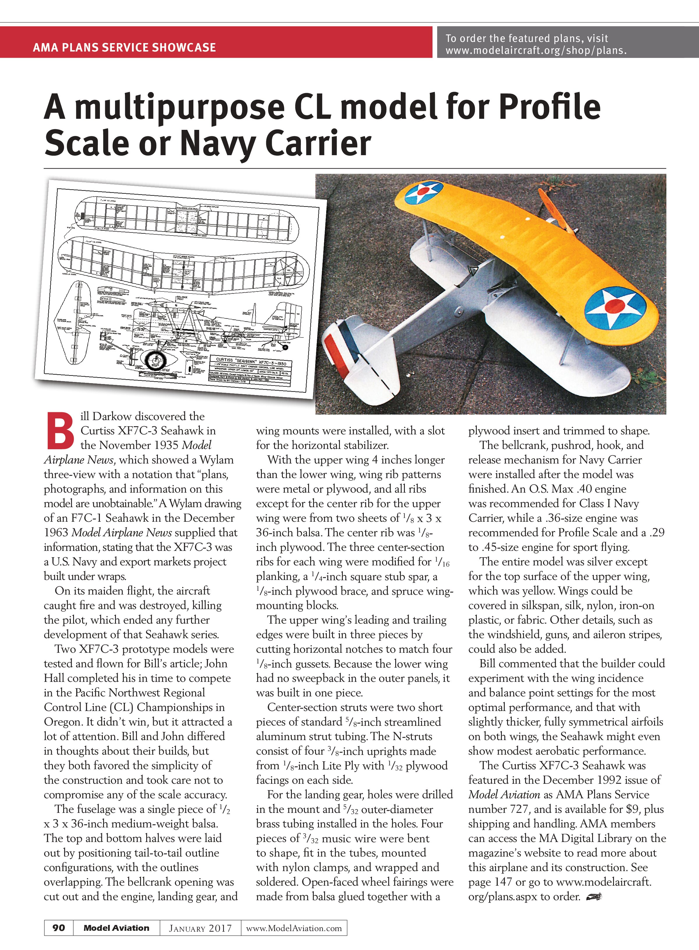
The fuselage was a single piece of ½ x 3 x 36-inch medium-weight balsa. The top and bottom halves were laid out by positioning tail-to-tail outline configurations, with the outlines overlapping. The bellcrank opening was cut out and the engine, landing gear, and wing mounts were installed, with a slot for the horizontal stabilizer.
With the upper wing 4 inches longer than the lower wing, wing rib patterns were metal or plywood, and all ribs except for the center rib for the upper wing were from two sheets of ⅛ x 3 x 36-inch balsa. The center rib was ⅛-inch plywood. The three center-section ribs for each wing were modified for ¹⁄₁₆ planking, a ¼-inch square stub spar, a ⅛-inch plywood brace, and spruce wing-mounting blocks.
The upper wing’s leading and trailing edges were built in three pieces by cutting horizontal notches to match four ⅛-inch gussets. Because the lower wing had no sweepback in the outer panels, it was built in one piece.
Center-section struts were two short pieces of standard ⅝-inch streamlined aluminum strut tubing. The N-struts consist of four ⅜-inch uprights made from ⅛-inch Lite Ply with ¹⁄₃₂ plywood facings on each side.
For the landing gear, holes were drilled in the mount and ⁵⁄₃₂ outer-diameter brass tubing installed in the holes. Four pieces of ³⁄₃₂ music wire were bent to shape, fit in the tubes, mounted with nylon clamps, and wrapped and soldered. Open-faced wheel fairings were made from balsa glued together with a plywood insert and trimmed to shape.
The bellcrank, pushrod, hook, and release mechanism for Navy Carrier were installed after the model was finished. An O.S. Max .40 engine was recommended for Class I Navy Carrier, while a .36-size engine was recommended for Profile Scale and a .29 to .45-size engine for sport flying.
The entire model was silver except for the top surface of the upper wing, which was yellow. Wings could be covered in silkspan, silk, nylon, iron-on plastic, or fabric. Other details, such as the windshield, guns, and aileron stripes, could also be added.
Bill commented that the builder could experiment with the wing incidence and balance point settings for the most optimal performance, and that with slightly thicker, fully symmetrical airfoils on both wings, the Seahawk might even show modest aerobatic performance.
The Curtiss XF7C-3 Seahawk was featured in the December 1992 issue of Model Aviation as AMA Plans Service number 727, and is available for $9, plus shipping and handling. AMA members can access the MA Digital Library on the magazine’s website to read more about this airplane and its construction. See page 147 or go to www.modelaircraft.org/plans.aspx to order.