Engine mounting and thrust angles
by John Glezellis
jglezellis@gmail.com
During the first few flights on a Giant Scale aerobatic model, it is mandatory for a pilot to allocate time to properly tune the aircraft to correct for any undesired flight characteristics. The entire trimming process, however, must occur in a procedural fashion.
You must determine the proper center of gravity, laterally balance the model, determine the correct thrust angles for the engine, adjust the wing and horizontal stabilizer incidence, adjust specific rates, and implement any required programmable mixes. Performing one step out of sequence can impact the tuning process and will require revisiting earlier tests.
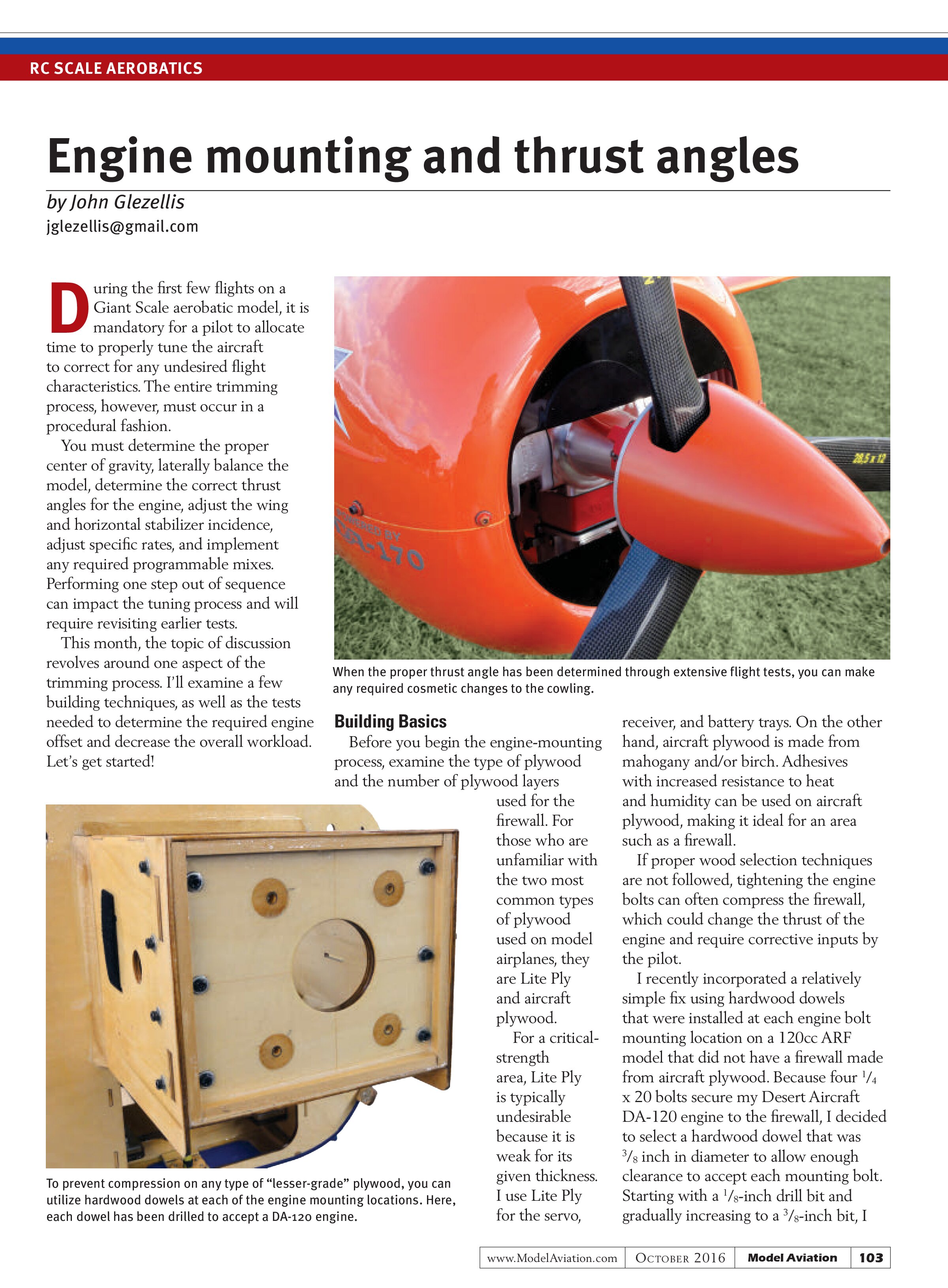
This month, the topic of discussion revolves around one aspect of the trimming process. I’ll examine a few building techniques, as well as the tests needed to determine the required engine offset and decrease the overall workload. Let’s get started!


Building Basics
Before you begin the engine-mounting process, examine the type of plywood and the number of plywood layers used for the firewall. For those who are unfamiliar with the two most common types of plywood used on model airplanes, they are Lite Ply and aircraft plywood.
For a critical-strength area, Lite Ply is typically undesirable because it is weak for its given thickness. I use Lite Ply for the servo, receiver, and battery trays. On the other hand, aircraft plywood is made from mahogany and/or birch. Adhesives with increased resistance to heat and humidity can be used on aircraft plywood, making it ideal for an area such as a firewall.
If proper wood selection techniques are not followed, tightening the engine bolts can often compress the firewall, which could change the thrust of the engine and require corrective inputs by the pilot.
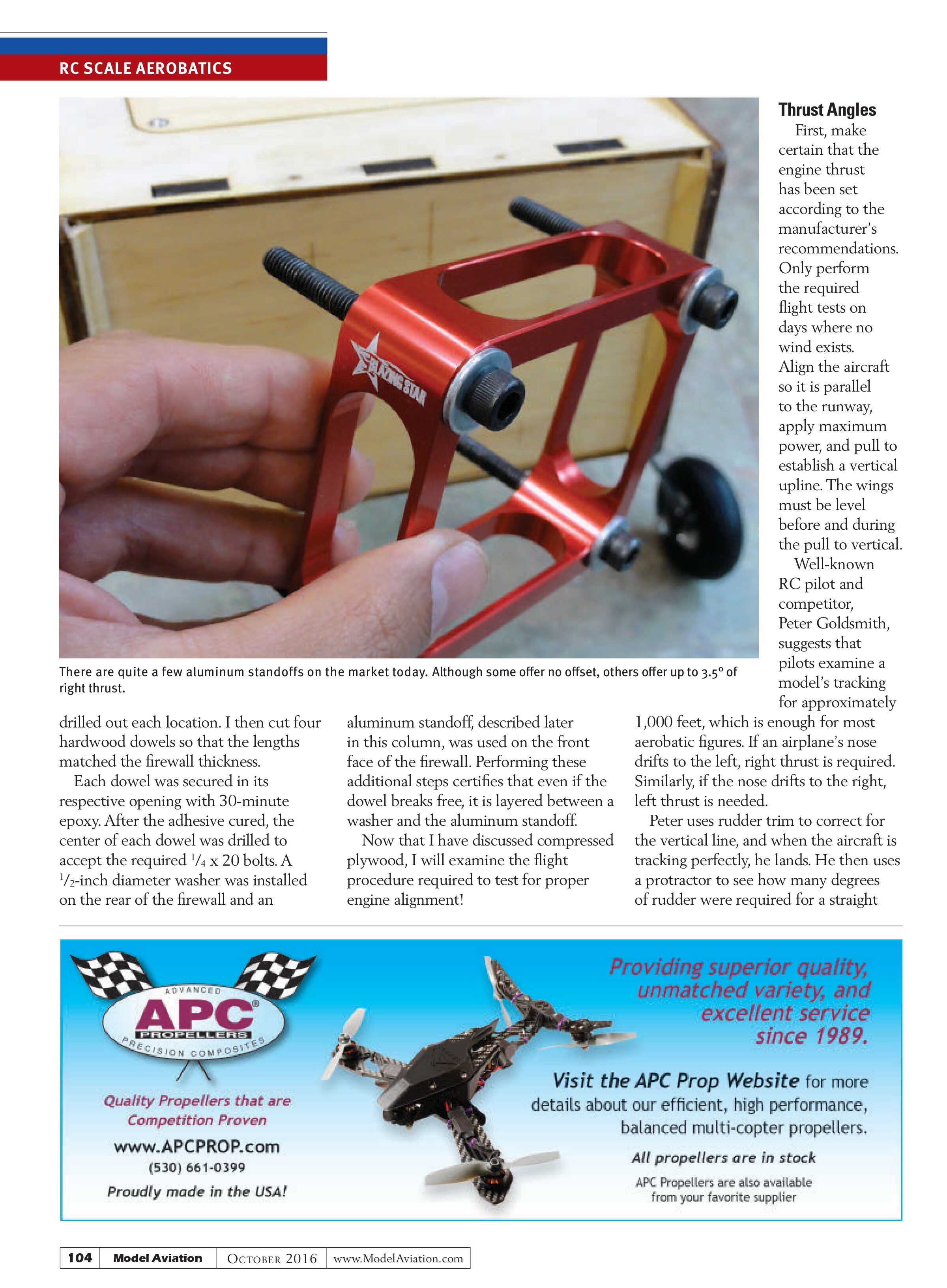
I recently incorporated a relatively simple fix using hardwood dowels that were installed at each engine bolt mounting location on a 120cc ARF model that did not have a firewall made from aircraft plywood. Because four ¼ x 20 bolts secure my Desert Aircraft DA-120 engine to the firewall, I decided to select a hardwood dowel that was ⅜ inch in diameter to allow enough clearance to accept each mounting bolt. Starting with a ⅛-inch drill bit and gradually increasing to a ⅜-inch bit, I
drilled out each location. I then cut four hardwood dowels so that the lengths matched the firewall thickness.
Each dowel was secured in its respective opening with 30-minute epoxy. After the adhesive cured, the center of each dowel was drilled to accept the required ¼ x 20 bolts. A ½-inch diameter washer was installed on the rear of the firewall and an aluminum standoff, described later in this column, was used on the front face of the firewall. Performing these additional steps certifies that even if the dowel breaks free, it is layered between a washer and the aluminum standoff.
Now that I have discussed compressed plywood, I will examine the flight procedure required to test for proper engine alignment!

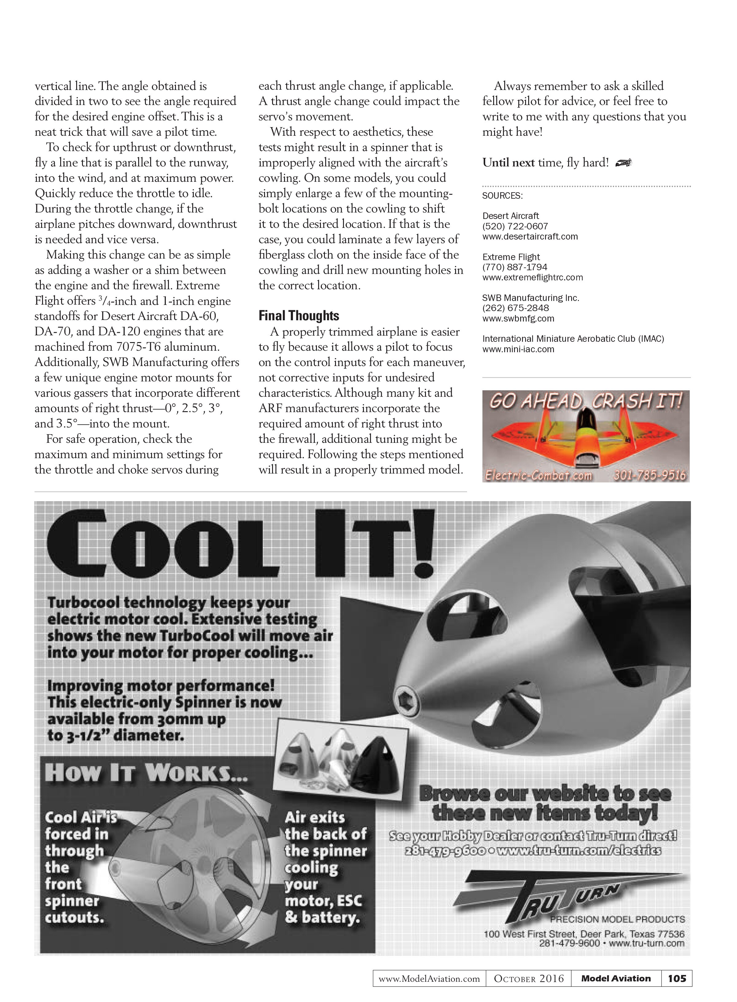
There are quite a few aluminum standoffs on the market today. Although some offer no offset, others offer up to 3.5° of right thrust.
Thrust Angles
First, make certain that the engine thrust has been set according to the manufacturer’s recommendations. Only perform the required flight tests on days where no wind exists. Align the aircraft so it is parallel to the runway, apply maximum power, and pull to establish a vertical upline. The wings must be level before and during the pull to vertical. Well-known RC pilot and competitor, Peter Goldsmith, suggests that pilots examine a model’s tracking for approximately 1,000 feet, which is enough for most aerobatic figures. If an airplane’s nose drifts to the left, right thrust is required. Similarly, if the nose drifts to the right, left thrust is needed.
Peter uses rudder trim to correct for the vertical line, and when the aircraft is tracking perfectly, he lands. He then uses a protractor to see how many degrees of rudder were required for a straight vertical line. The angle obtained is divided in two to see the angle required for the desired engine offset. This is a neat trick that will save a pilot time.
To check for upthrust or downthrust, fly a line that is parallel to the runway, into the wind, and at maximum power. Quickly reduce the throttle to idle. During the throttle change, if the airplane pitches downward, downthrust is needed and vice versa.
Making this change can be as simple as adding a washer or a shim between the engine and the firewall. Extreme Flight offers ¾-inch and 1-inch engine standoffs for Desert Aircraft DA-60, DA-70, and DA-120 engines that are machined from 7075-T6 aluminum. Additionally, SWB Manufacturing offers a few unique engine motor mounts for various gassers that incorporate different amounts of right thrust—0°, 2.5°, 3°, and 3.5°—into the mount.
For safe operation, check the maximum and minimum settings for the throttle and choke servos during each thrust angle change, if applicable. A thrust angle change could impact the servo’s movement.
With respect to aesthetics, these tests might result in a spinner that is improperly aligned with the aircraft’s cowling. On some models, you could simply enlarge a few of the mounting-bolt locations on the cowling to shift it to the desired location. If that is the case, you could laminate a few layers of fiberglass cloth on the inside face of the cowling and drill new mounting holes in the correct location.
Final Thoughts
A properly trimmed airplane is easier to fly because it allows a pilot to focus on the control inputs for each maneuver, not corrective inputs for undesired characteristics. Although many kit and ARF manufacturers incorporate the required amount of right thrust into the firewall, additional tuning might be required. Following the steps mentioned will result in a properly trimmed model.
Always remember to ask a skilled fellow pilot for advice, or feel free to write to me with any questions that you might have!
Until next time, fly hard!
SOURCES:
Desert Aircraft
(520) 722-0607
www.desertaircraft.com
Extreme Flight
(770) 887-1794
www.extremeflightrc.com
SWB Manufacturing Inc.
(262) 675-2848
www.swbmfg.com
International Miniature Aerobatic Club (IMAC)
www.mini-iac.com