Uniflow fuel tanks
Bob Angel

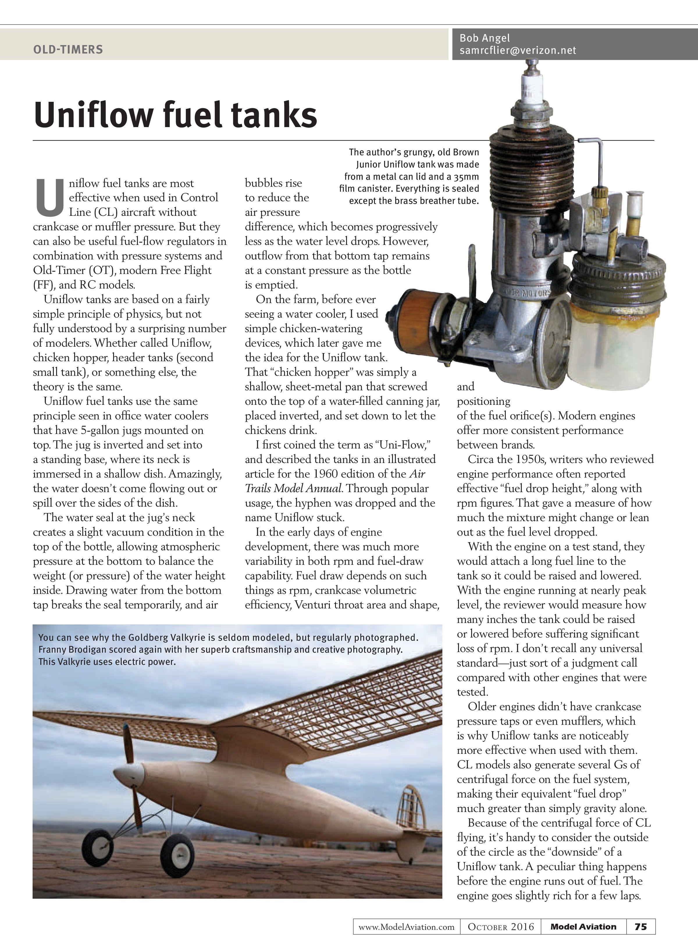
Uniflow fuel tanks are most effective when used in Control Line (CL) aircraft without crankcase or muffler pressure. But they can also be useful fuel-flow regulators in combination with pressure systems and Old-Timer (OT), modern Free Flight (FF), and RC models.
Uniflow tanks are based on a fairly simple principle of physics, but not fully understood by a surprising number of modelers. Whether called Uniflow, chicken hopper, header tanks (second small tank), or something else, the theory is the same.
Uniflow fuel tanks use the same principle seen in office water coolers that have 5-gallon jugs mounted on top. The jug is inverted and set into a standing base, where its neck is immersed in a shallow dish. Amazingly, the water doesn’t come flowing out or spill over the sides of the dish.
The water seal at the jug’s neck creates a slight vacuum condition in the top of the bottle, allowing atmospheric pressure at the bottom to balance the weight (or pressure) of the water height inside. Drawing water from the bottom tap breaks the seal temporarily, and air bubbles rise to reduce the air pressure difference, which becomes progressively less as the water level drops. However, outflow from that bottom tap remains at a constant pressure as the bottle is emptied.
On the farm, before ever seeing a water cooler, I used simple chicken-watering devices, which later gave me the idea for the Uniflow tank. That “chicken hopper” was simply a shallow, sheet-metal pan that screwed onto the top of a water-filled canning jar, placed inverted, and set down to let the chickens drink.
I first coined the term as “Uni-Flow,” and described the tanks in an illustrated article for the 1960 edition of the Air Trails Model Annual. Through popular usage, the hyphen was dropped and the name Uniflow stuck.
In the early days of engine development, there was much more variability in both rpm and fuel-draw capability. Fuel draw depends on such things as rpm, crankcase volumetric efficiency, Venturi throat area and shape, and positioning of the fuel orifice(s). Modern engines offer more consistent performance between brands.
Circa the 1950s, writers who reviewed engine performance often reported effective “fuel drop height,” along with rpm figures. That gave a measure of how much the mixture might change or lean out as the fuel level dropped.
With the engine on a test stand, they would attach a long fuel line to the tank so it could be raised and lowered. With the engine running at nearly peak level, the reviewer would measure how many inches the tank could be raised or lowered before suffering significant loss of rpm. I don’t recall any universal standard—just sort of a judgment call compared with other engines that were tested.
Older engines didn’t have crankcase pressure taps or even mufflers, which is why Uniflow tanks are noticeably more effective when used with them. CL models also generate several Gs of centrifugal force on the fuel system, making their equivalent “fuel drop” much greater than simply gravity alone.
Because of the centrifugal force of CL flying, it’s handy to consider the outside of the circle as the “downside” of a Uniflow tank. A peculiar thing happens before the engine runs out of fuel. The engine goes slightly rich for a few laps.

That’s usually a good thing for sport or Precision flying. It allows the engine to relax and cool somewhat, while notifying the flier to prepare to land. The reason for the final richening effect is because the Uniflow vent is normally uncovered slightly before the fuel pickup draws the last of the fuel. When that vent is uncovered, the last of the bubbles disappear and the vent line is open to the atmosphere.
Bubbles have surface tension, which acts as a slight pressure retardant until they disappear. There are even several formulas to compute the surface tension of bubbles, depending on fluid viscosity, the size of the bubble, and the shape of its exit hole.
Using engine pressure, you can still set up a tank as Uniflow. You merely immerse the pressure line down toward the level of the fuel pickup tube. With an aerobatic RC aircraft, “down” is a relative term, making the Uniflow vent harder to maintain when it is immersed. That’s usually done by using a separate flex line and a clunk that is shorter than the fuel pickup line. The two lines are often linked loosely together.
The reason the regulating effect of the Uniflow tank is less than when using a pressure tank is because the pressure system itself has already raised the fuel pressure well above the atmospheric pressure, so regulating atmospheric pressure change via a Uniflow tank has less effect percentagewise.
What about OT, FF, and RC? The same rules apply when engine pressure is used. Because most of our antique engines don’t use pressure, they have a slight advantage using a Uniflow tank.
Texaco fliers particularly like using Uniflow tanks.
The ½A Texaco event for OT RC once required using a Cox 8cc fuel tank. Some of the tanks for the Black Widow, Golden Bee, etc., had a pair of CL Aerobatics-type vents. That’s one vent on top reaching to the tank bottom, and another at the bottom, reaching up near the inside top. After filling, some fliers would cap off the top vent to prevent fuel siphoning. Few realized, however, that if you sealed that bottom vent instead, you had a Uniflow tank.
I normally sealed the bottom vent. Although it helped prevent fuel siphoning, the Uniflow advantage wasn’t dramatic on those engines. There are probably a couple of reasons for that. Cox engines already draw fuel well from that short tank.
We also rise several hundred feet during the engine run. Any engine’s ideal fuel mixture calls for a leaner needle setting as altitude is gained in order to balance the thinner air supply. I’ve even seen charts for automobile engines that show what leaner-size carburetor jets should be used for operation at various higher-altitude levels.
For OT flying, a regular (non-Uniflow) tank and a fixed needle-valve setting allow the mixture to lean itself slightly as the tank empties. That helps compensate slightly for altitude gain.
Should you use a Uniflow tank in your OT aircraft? I won’t try to tell you what to do because you might be competing with me, but when I’m setting up a tank, I “go with the flow.”
Upcoming OT Events
If you want your OT event listed in my column, make sure you send it to me at least four months before it is scheduled. This will take into account the column’s lead time, plus the fact that it runs bimonthly.
The 41st running of the annual John Pond Commemorative OT RC contest will be held October 22-23, 2016, at the Greenfield Fliers’ field near Bakersfield, California.
The Southwest Regionals for OT, FF, and RC events, plus AMA FF and FAI FF, is scheduled for January 14-16, 2017, Martin Luther King Jr. holiday weekend, in Eloy, Arizona.
Check the AMA Sanctioned Event Calendar for details.
SOURCES:
Brodak Manufacturing Company, Inc.
(724) 966-2726
www.brodak.com
AMA Event Calendar
www.modelaircraft.org/events/calendar.aspx