Build a Messerschmitt Bf 109
by Paul Kohlmann
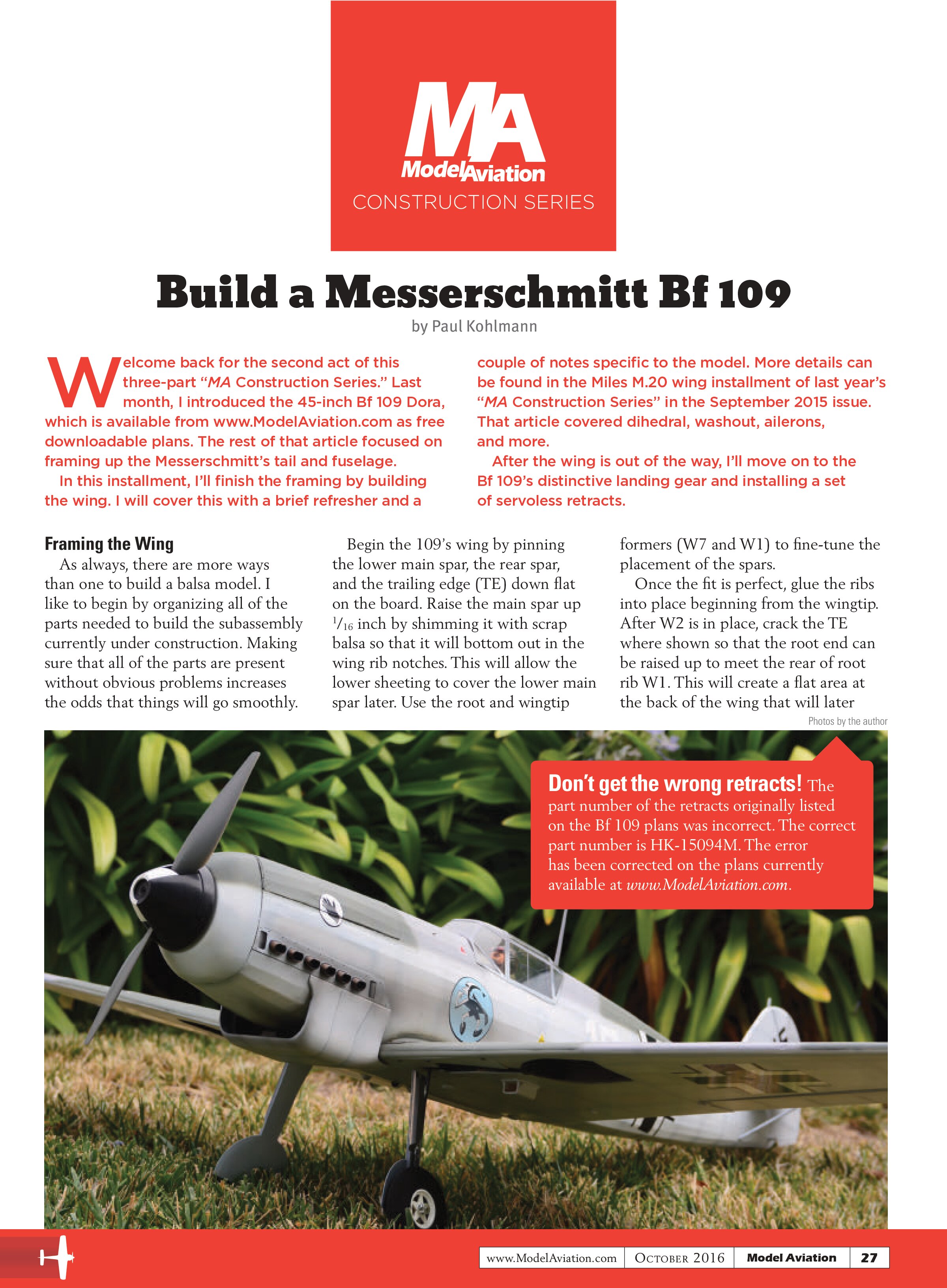
Welcome back for the second act of this three-part “MA Construction Series.” Last month, I introduced the 45-inch Bf 109 Dora, which is available from www.ModelAviation.com as free downloadable plans. The rest of that article focused on framing up the Messerschmitt’s tail and fuselage. In this installment, I’ll finish the framing by building the wing. I will cover this with a brief refresher and a couple of notes specific to the model. More details can be found in the Miles M.20 wing installment of last year’s “MA Construction Series” in the September 2015 issue. That article covered dihedral, washout, ailerons, and more. After the wing is out of the way, I’ll move on to the Bf 109’s distinctive landing gear and installing a set of servoless retracts.
Framing the Wing
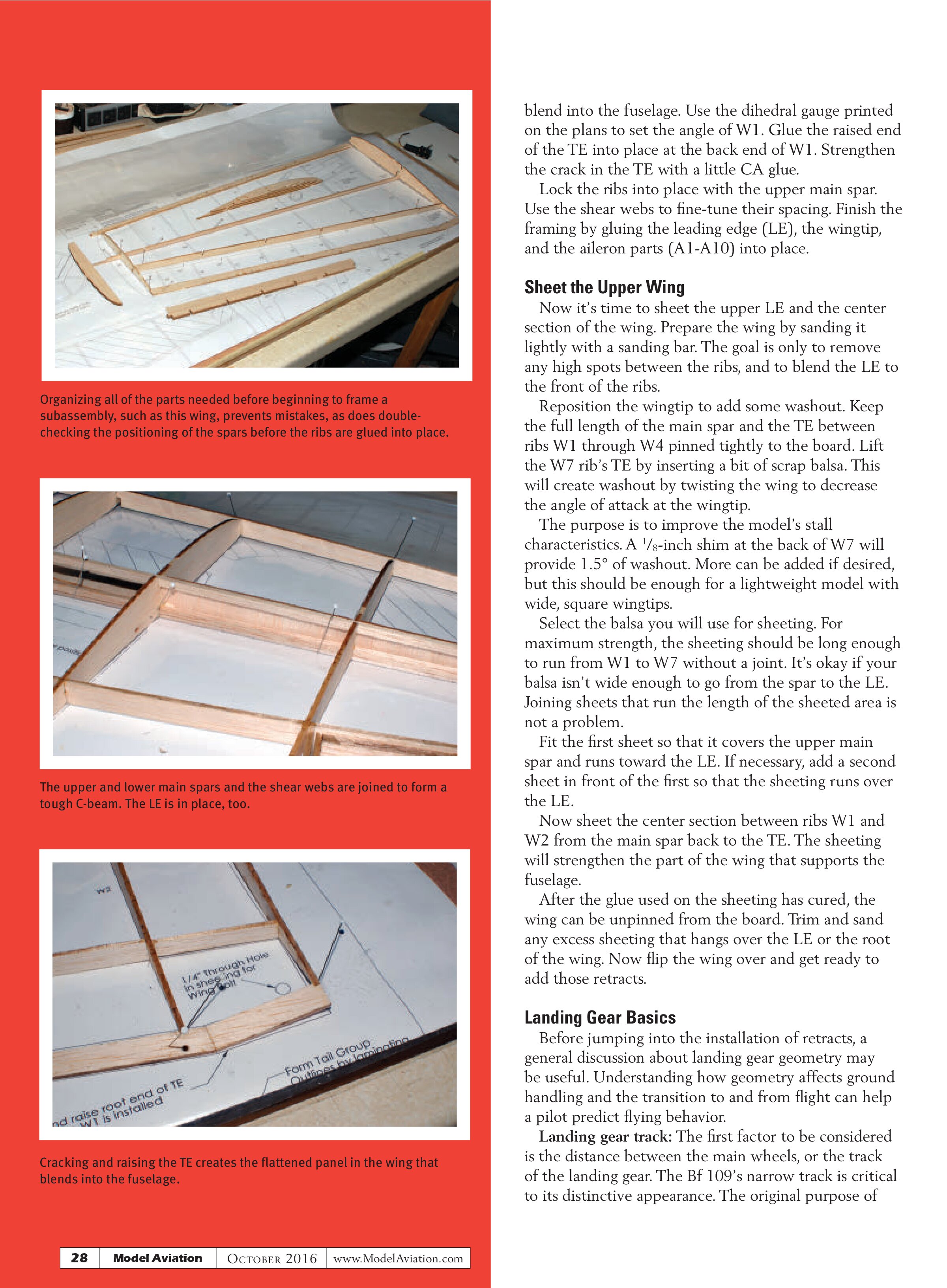
As always, there are more ways than one to build a balsa model. I like to begin by organizing all of the parts needed to build the subassembly currently under construction. Making sure that all of the parts are present without obvious problems increases the odds that things will go smoothly.
Begin the 109’s wing by pinning the lower main spar, the rear spar, and the trailing edge (TE) down flat on the board. Raise the main spar up 1/16 inch by shimming it with scrap balsa so that it will bottom out in the wing rib notches. This will allow the lower sheeting to cover the lower main spar later. Use the root and wingtip formers (W7 and W1) to fine-tune the placement of the spars.
Once the fit is perfect, glue the ribs into place beginning from the wingtip. After W2 is in place, crack the TE where shown so that the root end can be raised up to meet the rear of root rib W1. This will create a flat area at the back of the wing that will later

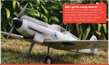
Don’t get the wrong retracts! The part number of the retracts originally listed on the Bf 109 plans was incorrect. The correct part number is HK-15094M. The error has been corrected on the plans currently available at www.ModelAviation.com.
blend into the fuselage. Use the dihedral gauge printed on the plans to set the angle of W1. Glue the raised end of the TE into place at the back end of W1. Strengthen the crack in the TE with a little CA glue.
Lock the ribs into place with the upper main spar. Use the shear webs to fine-tune their spacing. Finish the framing by gluing the leading edge (LE), the wingtip, and the aileron parts (A1-A10) into place.
Sheet the Upper Wing
Now it’s time to sheet the upper LE and the center section of the wing. Prepare the wing by sanding it lightly with a sanding bar. The goal is only to remove any high spots between the ribs, and to blend the LE to the front of the ribs.
Reposition the wingtip to add some washout. Keep the full length of the main spar and the TE between ribs W1 through W4 pinned tightly to the board. Lift the W7 rib’s TE by inserting a bit of scrap balsa. This will create washout by twisting the wing to decrease the angle of attack at the wingtip.
The purpose is to improve the model’s stall characteristics. A ⅛-inch shim at the back of W7 will provide 1.5° of washout. More can be added if desired, but this should be enough for a lightweight model with wide, square wingtips.
Select the balsa you will use for sheeting. For maximum strength, the sheeting should be long enough to run from W1 to W7 without a joint. It’s okay if your balsa isn’t wide enough to go from the spar to the LE. Joining sheets that run the length of the sheeted area is not a problem.
Fit the first sheet so that it covers the upper main spar and runs toward the LE. If necessary, add a second sheet in front of the first so that the sheeting runs over the LE.
Now sheet the center section between ribs W1 and W2 from the main spar back to the TE. The sheeting will strengthen the part of the wing that supports the fuselage.
After the glue used on the sheeting has cured, the wing can be unpinned from the board. Trim and sand any excess sheeting that hangs over the LE or the root of the wing. Now flip the wing over and get ready to add those retracts.
Landing Gear Basics
Before jumping into the installation of retracts, a general discussion about landing gear geometry may be useful. Understanding how geometry affects ground handling and the transition to and from flight can help a pilot predict flying behavior.
Landing gear track: The first factor to be considered is the distance between the main wheels, or the track of the landing gear. The Bf 109’s narrow track is critical to its distinctive appearance. The original purpose of this arrangement was to simplify the engine, wing, and landing gear mounting points into a coordinated assembly for mass production. This also allowed the wings to be removed for transport or maintenance while the rest of the airframe stood upright.
As is common in engineering, this landing gear arrangement was a compromise that also had negative effects. The narrow track drew thousands of pilots into ground loops. Interestingly, the Spitfire had an even narrower track, but it was much easier to handle on the ground. This brings us to the second factor.
Strut camber angle: The angle of the struts when the aircraft is viewed head on is closer to vertical on the Spitfire. This transferred more force into the airframe rather than the landing gear pivot point. The result was that a roughly handled Spitfire bounced less and experienced fewer broken legs than the Bf 109 with its outward-splayed struts.
Distance from center of gravity (CG): The third factor is the position of the wheels relative to the CG. The position of the wheels in the down position is determined by the location of the retract, by the forward angle of the strut, and by the length of the strut.
For a tail-dragger such as the Bf 109, keeping the wheels forward of the CG helps prevent nose-overs, but we don’t want to go overboard. Wheels positioned too far forward make an aircraft difficult to rotate on takeoff. A good rule of thumb is to locate the main wheels 12° to 15° in front of the CG.
Of course, on a scale model, our options are limited. We want to duplicate the appearance of the full-scale aircraft, but unless the goal is to compete in Scale events, we might take some liberties with the design to improve performance where a deficiency is known to exist.
In the case of the Bf 109, the landing gear geometry is quite close to stock with one key exception. The strut camber angles are closer to perpendicular as on the Spitfire. The main reason for this is that I couldn’t find an 85° retract that would fit in the thin, efficient airfoil that I prefer to use. But the upside is that this aircraft will be slightly more docile on the ground.
Installing Servoless Retracts
The retract units will be mounted to a light plywood framework that defines all of the geometry factors previously discussed. This framework fits between ribs W2 and W3. It also keys into the LE, the main spars, and the sheeting for maximum strength.
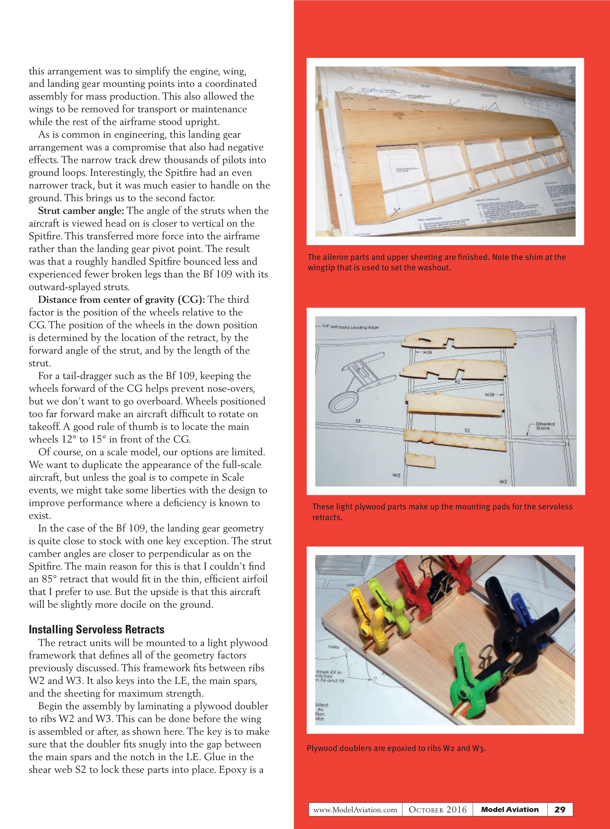
Begin the assembly by laminating a plywood doubler to ribs W2 and W3. This can be done before the wing is assembled or after, as shown here. The key is to make sure that the doubler fits snugly into the gap between the main spars and the notch in the LE. Glue in the shear web S2 to lock these parts into place. Epoxy is a


A view of the crossbars and mounting pads epoxied to the doubled ribs while the shear web is glued in.

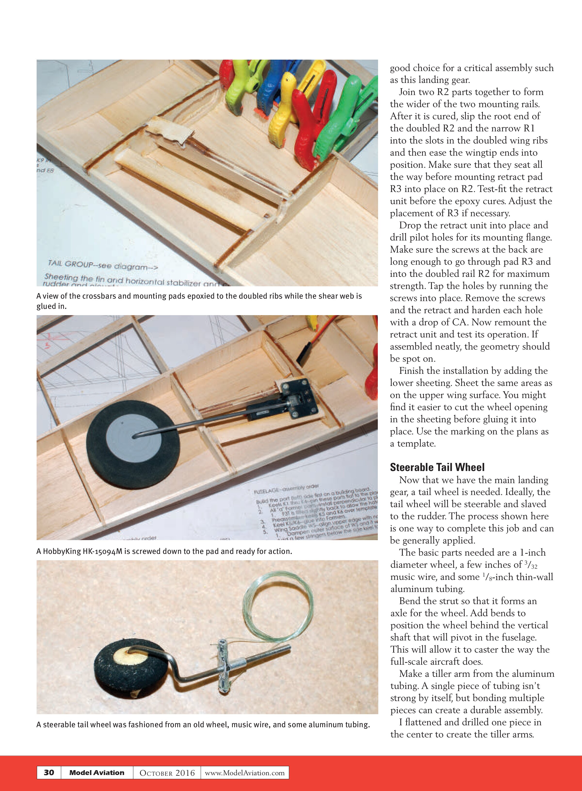
A HobbyKing HK-15094M is screwed down to the pad and ready for action.

A steerable tail wheel was fashioned from an old wheel, music wire, and some aluminum tubing.
good choice for a critical assembly such as this landing gear.
Join two R2 parts together to form the wider of the two mounting rails. After it is cured, slip the root end of the doubled R2 and the narrow R1 into the slots in the doubled wing ribs and then ease the wingtip ends into position. Make sure that they seat all the way before mounting retract pad R3 into place on R2. Test-fit the retract unit before the epoxy cures. Adjust the placement of R3 if necessary.
Drop the retract unit into place and drill pilot holes for its mounting flange. Make sure the screws at the back are long enough to go through pad R3 and into the doubled rail R2 for maximum strength. Tap the holes by running the screws into place. Remove the screws and the retract and harden each hole with a drop of CA. Now remount the retract unit and test its operation. If assembled neatly, the geometry should be spot on.
Finish the installation by adding the lower sheeting. Sheet the same areas as on the upper wing surface. You might find it easier to cut the wheel opening in the sheeting before gluing it into place. Use the marking on the plans as a template.
Steerable Tail Wheel
Now that we have the main landing gear, a tail wheel is needed. Ideally, the tail wheel will be steerable and slaved to the rudder. The process shown here is one way to complete this job and can be generally applied.
The basic parts needed are a 1-inch diameter wheel, a few inches of ³⁄₃₂ music wire, and some ⅛-inch thin-wall aluminum tubing.
Bend the strut so that it forms an axle for the wheel. Add bends to position the wheel behind the vertical shaft that will pivot in the fuselage. This will allow it to caster the way the full-scale aircraft does.
Make a tiller arm from the aluminum tubing. A single piece of tubing isn’t strong by itself, but bonding multiple pieces can create a durable assembly. I flattened and drilled one piece in the center to create the tiller arms.

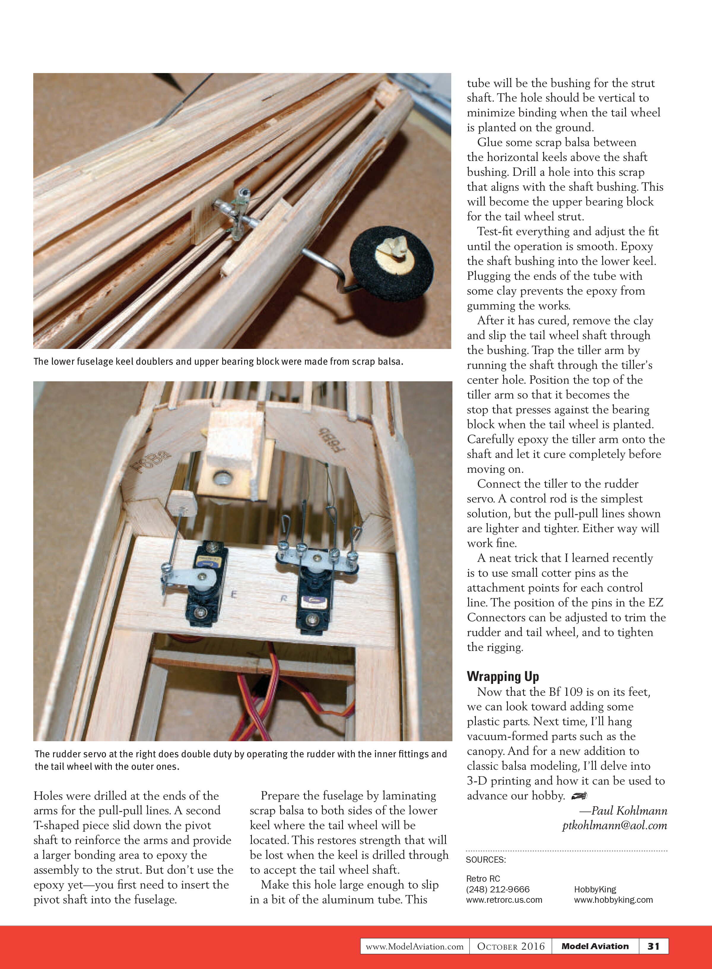
The lower fuselage keel doublers and upper bearing block were made from scrap balsa.

The rudder servo at the right does double duty by operating the rudder with the inner fittings and the tail wheel with the outer ones.
Holes were drilled at the ends of the arms for the pull-pull lines. A second T-shaped piece slid down the pivot shaft to reinforce the arms and provide a larger bonding area to epoxy the assembly to the strut. But don’t use the epoxy yet—you first need to insert the pivot shaft into the fuselage.
Prepare the fuselage by laminating scrap balsa to both sides of the lower keel where the tail wheel will be located. This restores strength that will be lost when the keel is drilled through to accept the tail wheel shaft.
Make this hole large enough to slip in a bit of the aluminum tube. This tube will be the bushing for the strut shaft. The hole should be vertical to minimize binding when the tail wheel is planted on the ground.
Glue some scrap balsa between the horizontal keels above the shaft bushing. Drill a hole into this scrap that aligns with the shaft bushing. This will become the upper bearing block for the tail wheel strut.
Test-fit everything and adjust the fit until the operation is smooth. Epoxy the shaft bushing into the lower keel. Plugging the ends of the tube with some clay prevents the epoxy from gumming the works.
After it has cured, remove the clay and slip the tail wheel shaft through the bushing. Trap the tiller arm by running the shaft through the tiller’s center hole. Position the top of the tiller arm so that it becomes the stop that presses against the bearing block when the tail wheel is planted. Carefully epoxy the tiller arm onto the shaft and let it cure completely before moving on.
Connect the tiller to the rudder servo. A control rod is the simplest solution, but the pull-pull lines shown are lighter and tighter. Either way will work fine.
A neat trick that I learned recently is to use small cotter pins as the attachment points for each control line. The position of the pins in the EZ Connectors can be adjusted to trim the rudder and tail wheel, and to tighten the rigging.
Wrapping Up
Now that the Bf 109 is on its feet, we can look toward adding some plastic parts. Next time, I’ll hang vacuum-formed parts such as the canopy. And for a new addition to classic balsa modeling, I’ll delve into 3-D printing and how it can be used to advance our hobby.
—Paul Kohlmann
ptkohlmann@aol.com
SOURCES:
Retro RC
(248) 212-9666
www.retrorc.us.com
HobbyKing
www.hobbyking.com