Arming plugs revisited
by Dick Perry
I received an email from Art Gillette following my April 2016 column in Model Aviation. The email discussed arming plugs for electric-powered models. Art noticed one photo with what appeared to be the negative (black) wire cut for the arming plug.
To repeat what I wrote in the text of the column, the arming plug should be in the positive (usually red) wire between the battery and any other equipment on the model. The female side of the arming plug should be on the wire directly connected to the battery, so that the “hot” part of the connector is completely surrounded by insulation.
Electric Carrier Project, Part Two
This month, I’ll discuss modifications to adapt an ARF RC model to Control Line (CL) Navy Carrier. I am using the

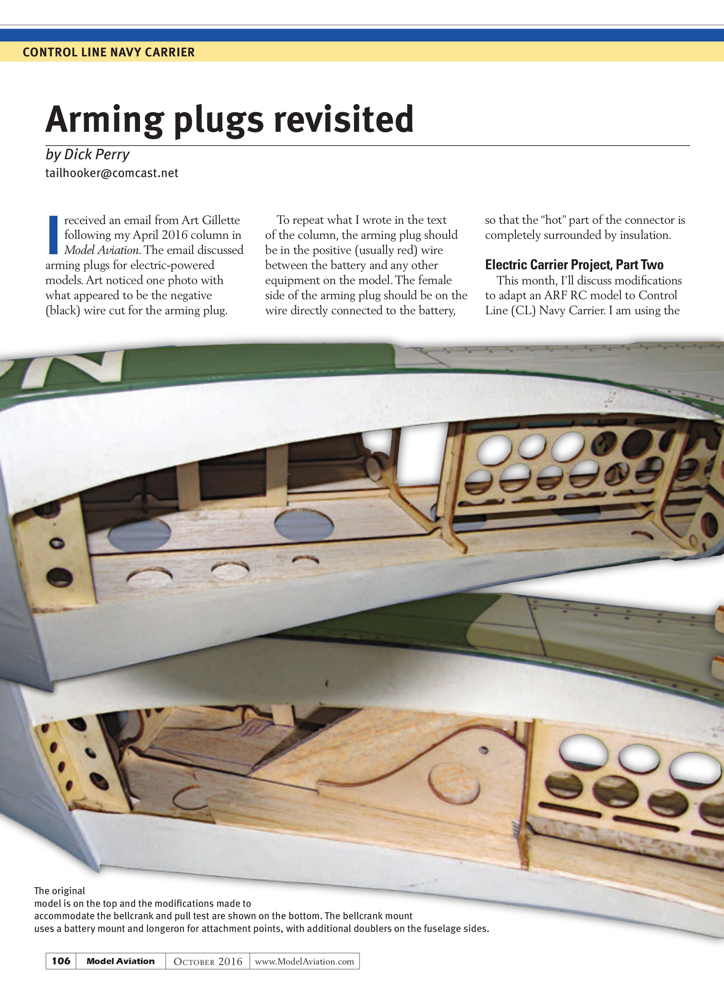
Caption: The original model is on the top and the modifications made to accommodate the bellcrank and pull test are shown on the bottom. The bellcrank mount uses a battery mount and longeron for attachment points, with additional doublers on the fuselage sides.
Supermarine Spitfire from HobbyKing. It is listed on the HobbyKing website, but was referred to as out of stock; however, it can be ordered as of July.
I was initially drawn to the Seafire because the clipped-wing variants, designed for low-altitude combat (ground attack), produced the largest wing area of any prototype I’ve found when built to an exact scale and a 44-inch wingspan. The HobbyKing Spitfire, with a wingspan of 49 inches, produced a clipped-wing Seafire at slightly less than a 44-inch wingspan.
The first thing I do before I order a model is use the basic information provided by the distributor to check the dimensions. I compare the wingspan, wing area, and the length of the model to the prototype to see if those dimensions match my three-view drawings.
The length can be slightly uncertain with spinners, engine shafts, etc. adding some question to the dimensions, but it’s all I have to work from at this early stage. Comparing wingspan to area tells me if the wing shape has been altered. All three of the dimensions on the HobbyKing model

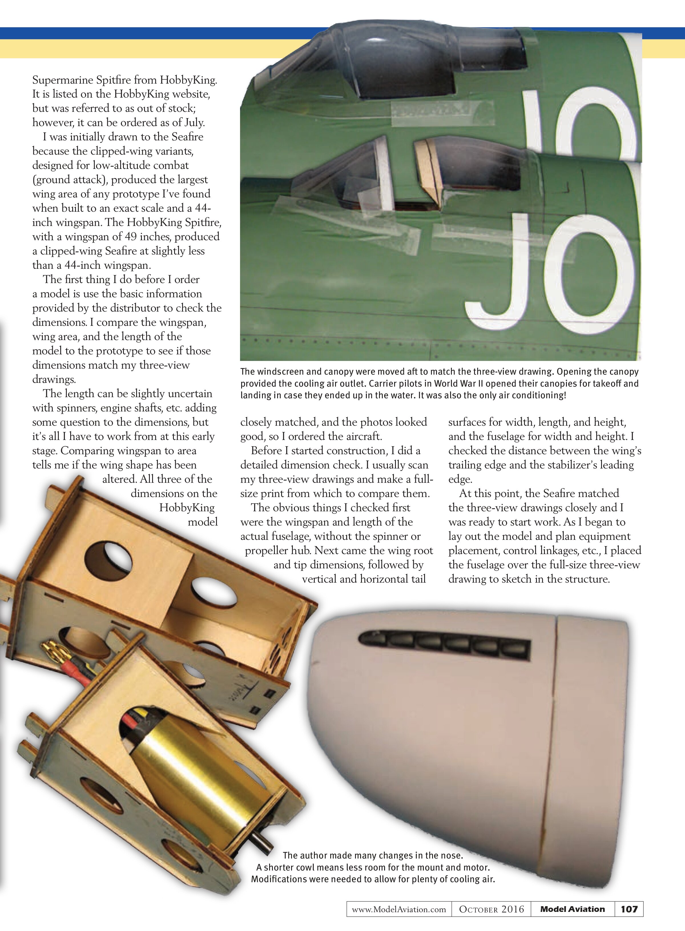
Caption: The windscreen and canopy were moved aft to match the three-view drawing. Opening the canopy provided the cooling air outlet. Carrier pilots in World War II opened their canopies for takeoff and landing in case they ended up in the water. It was also the only air conditioning!
closely matched, and the photos looked good, so I ordered the aircraft.
Before I started construction, I did a detailed dimension check. I usually scan my three-view drawings and make a full-size print from which to compare them.
The obvious things I checked first were the wingspan and length of the actual fuselage, without the spinner or propeller hub. Next came the wing root and tip dimensions, followed by vertical and horizontal tail surfaces for width, length, and height, and the fuselage for width and height. I checked the distance between the wing’s trailing edge and the stabilizer’s leading edge.
At this point, the Seafire matched the three-view drawings closely and I was ready to start work. As I began to lay out the model and plan equipment placement, control linkages, etc., I placed the fuselage over the full-size three-view drawing to sketch in the structure.


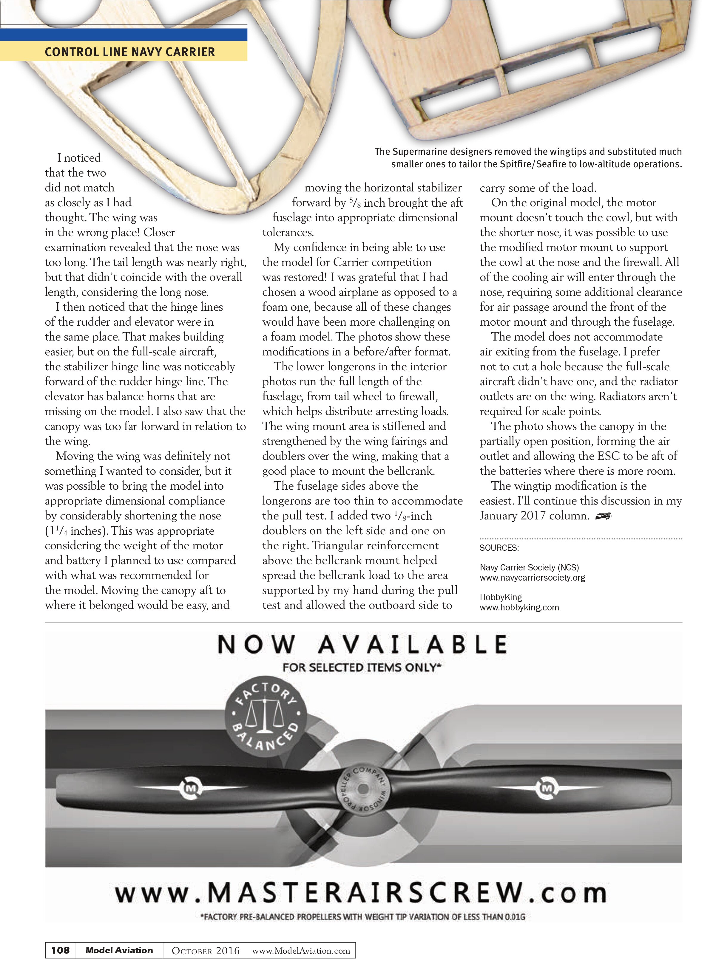
Caption: The author made many changes in the nose. A shorter cowl means less room for the mount and motor. Modifications were needed to allow for plenty of cooling air.

I noticed that the two did not match as closely as I had thought. The wing was in the wrong place! Closer examination revealed that the nose was too long. The tail length was nearly right, but that didn’t coincide with the overall length, considering the long nose.
I then noticed that the hinge lines of the rudder and elevator were in the same place. That makes building easier, but on the full-scale aircraft, the stabilizer hinge line was noticeably forward of the rudder hinge line. The elevator has balance horns that are missing on the model. I also saw that the canopy was too far forward in relation to the wing.
Moving the wing was definitely not something I wanted to consider, but it was possible to bring the model into appropriate dimensional compliance by considerably shortening the nose (1¼ inches). This was appropriate considering the weight of the motor and battery I planned to use compared with what was recommended for the model. Moving the canopy aft to where it belonged would be easy, and moving the horizontal stabilizer forward by ⅝ inch brought the aft fuselage into appropriate dimensional tolerances.
My confidence in being able to use the model for Carrier competition was restored! I was grateful that I had chosen a wood airplane as opposed to a foam one, because all of these changes would have been more challenging on a foam model. The photos show these modifications in a before/after format.
The lower longerons in the interior photos run the full length of the fuselage, from tail wheel to firewall, which helps distribute arresting loads. The wing mount area is stiffened and strengthened by the wing fairings and doublers over the wing, making that a good place to mount the bellcrank.
The fuselage sides above the longerons are too thin to accommodate the pull test. I added two ⅛-inch doublers on the left side and one on the right. Triangular reinforcement above the bellcrank mount helped spread the bellcrank load to the area supported by my hand during the pull test and allowed the outboard side to carry some of the load.
On the original model, the motor mount doesn’t touch the cowl, but with the shorter nose, it was possible to use the modified motor mount to support the cowl at the nose and the firewall. All of the cooling air will enter through the nose, requiring some additional clearance for air passage around the front of the motor mount and through the fuselage.
The model does not accommodate air exiting from the fuselage. I prefer not to cut a hole because the full-scale aircraft didn’t have one, and the radiator outlets are on the wing. Radiators aren’t required for scale points.
The photo shows the canopy in the partially open position, forming the air outlet and allowing the ESC to be aft of the batteries where there is more room.
The wingtip modification is the easiest. I’ll continue this discussion in my January 2017 column.
SOURCES:
Navy Carrier Society (NCS)
www.navycarriersociety.org
HobbyKing
www.hobbyking.com