2.4 GHz receiver antennae and carbon-fiber sailplanes
by Gordon Buckland
gordon@gatorf3b.com
Carbon fiber completely blankets our 2.4 GHz signals. To work effectively, the transmitter antenna must always have a direct line-of-sight path to at least one of the receiver antennae.
The current crop of sailplanes is stronger and lighter because of the extensive use of this wonder material in constructing the wings and fuselage. As a result, we have had to change the way we install our antennae to ensure that a flawless signal is always received.
When I switched from FM to 2.4 GHz a few years ago (I was a slow convert), I researched the issue and sought the advice of experts to ensure that I wouldn’t have a problem. Peter Goldsmith, of Horizon Hobby, gave me the best advice. He said, “Use the 10% rule when you choose a receiver. If your model is worth $2,000, spend $200 on the best receiver for the job.”
I also studied a great article in the April 2011 edition of Radio Controlled Soaring Digest by Sherman

Knight. Sherman did the research and helped others implement a safe internal installation on carbon-fiber-wing models with 2.4 GHz-friendly fuselages. His method uses the XYZ arrangement of three antennae routed in plastic tubes. There is one for each axis: a horizontal tube along the fuselage, a vertical tube, and a tube at 90° from left to right across the fuselage.
Sherman’s system is easy to install—with a straight tube forward under the battery, another bent tube under and vertically up through the servo tray, and the third forward and across the top of the fuselage ahead of the canopy. I have used this method with Spektrum AR9300 Carbon Fuselage Receivers without a single problem for four years. It makes accurate routing of each antenna a cinch and works great.
What do we do when the fuselage is entirely made of carbon fiber and is far from 2.4 GHz friendly? Whiskers permanently glued through the fuselage to get the 31mm of critical antenna outside can easily be damaged during transport.
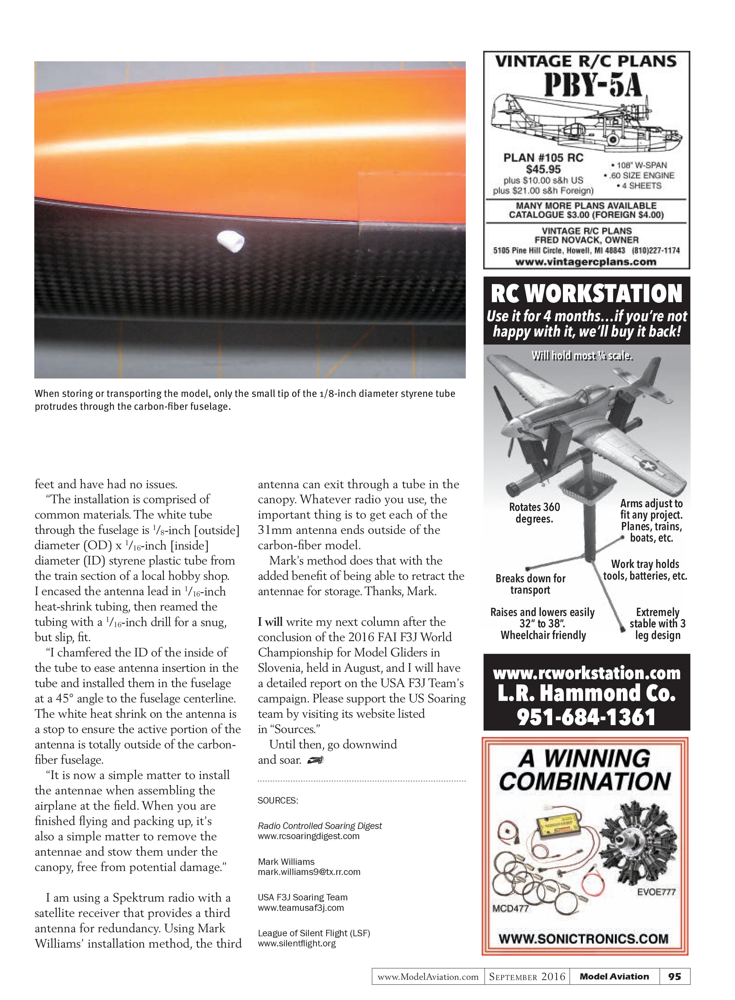
Mark Williams, from Texas, has detailed a nice alternative method, and I have reproduced his explanation about the 2.4 GHz antenna installation with his permission. Mark’s installation allows the antennae whiskers to hang securely outside of the model’s carbon-fiber fuselage, but they are retractable for transport to prevent damage. It is a neat and simple

system that totally makes sense.
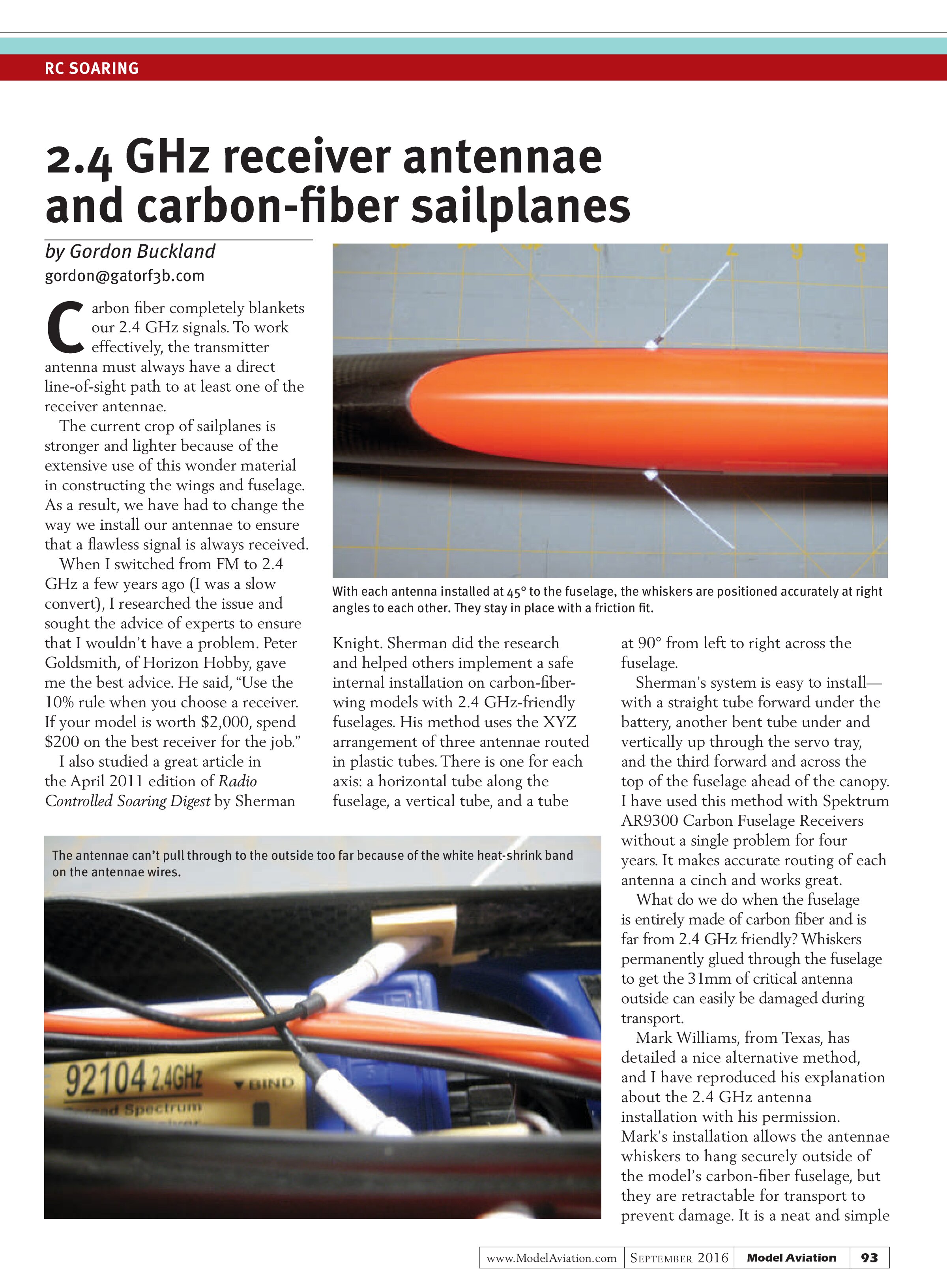
“I recently put together a new X3 with an all-carbon-fiber fuselage and I wanted a better 2.4 GHz antenna installation than I had used in the past for the [antenna] whiskers. My previous installations had exposed the fragile antennas to damage during transportation.
“At our recent monthly contest, I gave the X3 its first contest flights with the new antenna installation without any problems. This was the first time I had used this idea and as such, it was really a proof-of-concept installation. After using the system, I’ve been quite pleased. During subsequent contests, I have had my X3 way downwind at 1,600-plus

[[caption stored with figure]]

[[caption stored with figure]]
feet and have had no issues.
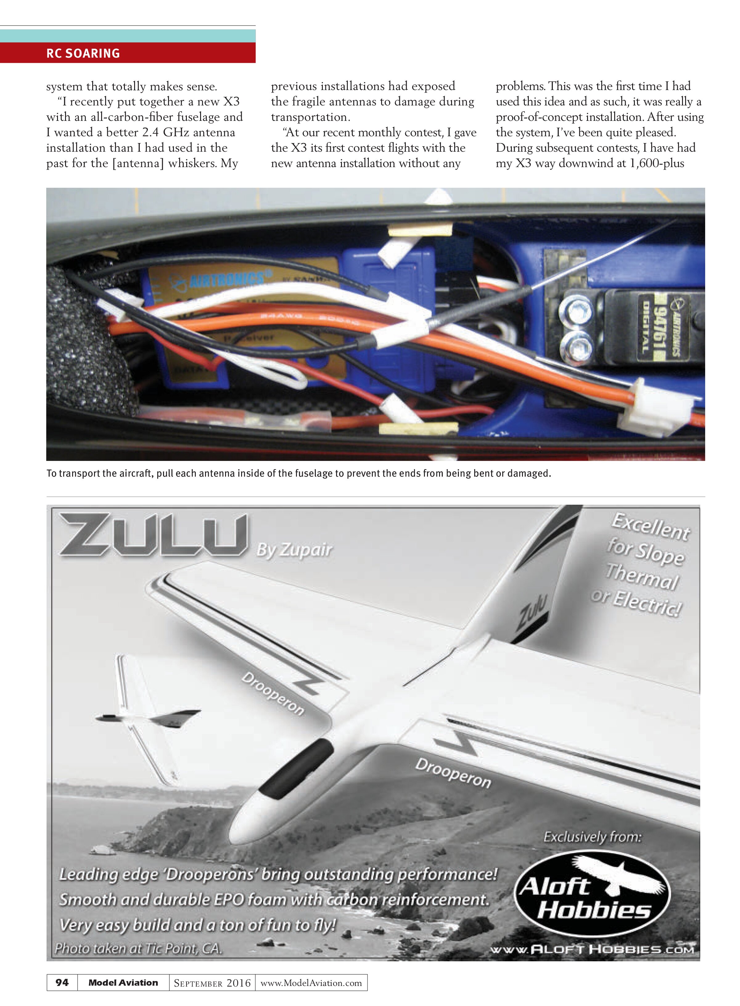
“The installation is comprised of common materials. The white tube through the fuselage is 1/8-inch [outside] diameter (OD) x 1/16-inch [inside] diameter (ID) styrene plastic tube from the train section of a local hobby shop. I encased the antenna lead in 1/16-inch heat-shrink tubing, then reamed the tubing with a 1/16-inch drill for a snug, but slip, fit.
“I chamfered the ID of the inside of the tube to ease antenna insertion in the tube and installed them in the fuselage at a 45° angle to the fuselage centerline. The white heat shrink on the antenna is a stop to ensure the active portion of the antenna is totally outside of the carbon-fiber fuselage.
“It is now a simple matter to install the antennae when assembling the airplane at the field. When you are finished flying and packing up, it’s also a simple matter to remove the antennae and stow them under the canopy, free from potential damage.”
I am using a Spektrum radio with a satellite receiver that provides a third antenna for redundancy. Using Mark Williams’ installation method, the third antenna can exit through a tube in the canopy. Whatever radio you use, the important thing is to get each of the 31mm antenna ends outside of the carbon-fiber model.
Mark’s method does that with the added benefit of being able to retract the antennae for storage. Thanks, Mark.
I will write my next column after the conclusion of the 2016 FAI F3J World Championship for Model Gliders in Slovenia, held in August, and I will have a detailed report on the USA F3J Team’s campaign. Please support the US Soaring team by visiting its website listed in “Sources.”
Until then, go downwind and soar.
SOURCES:
Radio Controlled Soaring Digest
www.rcsoaringdigest.com
Mark Williams
mark.williams9@tx.rr.com
USA F3J Soaring Team
www.teamusaf3j.com
League of Silent Flight (LSF)
www.silentflight.org