Aileron differential
by John Glezellis
jglezellis@gmail.com
Serious International Miniature Aerobatic Club (IMAC) pilots understand the importance of taking the time to properly trim and tune an airframe. The aircraft must respond to certain commands in a linear manner so that the pilot can focus on perfecting the routine at hand, instead of fighting the undesired tendencies that a poorly trimmed aircraft might exhibit.
This month’s topic is aileron differential. I will review the concept of differential and the benefit it offers RC Aerobatics pilots, and then I will transition to certain test practices and differential implementation. Finally, I will examine the importance of routine airplane maintenance for consistent performance.
Without further hesitation, let’s begin!
Aileron Differential Defined
Competition airplanes must be able to perform rolls as though the model were fastened to a string, and there should be no deviation in heading. Equal upward and downward travel on the aileron control surfaces can cause the aircraft to yaw in an undesired direction because of certain aerodynamic factors. Lift and drag are created on the wing panel with

the aileron moving downward when compared with the opposite wing. To correct this tendency, you can implement aileron differential.
Aileron differential is a function that results in different upward versus downward aileron deflection. In the most basic form, on a center-hinged wing, the application of left roll results in more deflection from the left aileron compared with the downward travel of the right aileron. By programming the proper percentage, you can eliminate any undesired tendency that most airplanes have in yaw during a roll.
The term “center-hinged” was mentioned for a reason. Top-hinged airframes, such as most composite airplanes, require reverse differential. An aileron that has more surface area has less upward deflection compared with a downward-moving aileron.
Before taking to the skies, you must guarantee that the upward and downward travel of each aileron is the same. If the deflection amount is off even by a degree, you will never find the proper differential percentage and a yaw tendency will always be present.
On the mechanical side, using multiple servos on a given control surface is common on 35% or larger Giant Scale aerobatic models. In the case of the Spektrum DX18 transmitter, a four-aileron servo wing type was selected. The distance from the center of the hinge line to the pivot point on the control horn must be the same as the distance from the center of the servo arm gear to the pivot point on the servo arm.
Because many wings

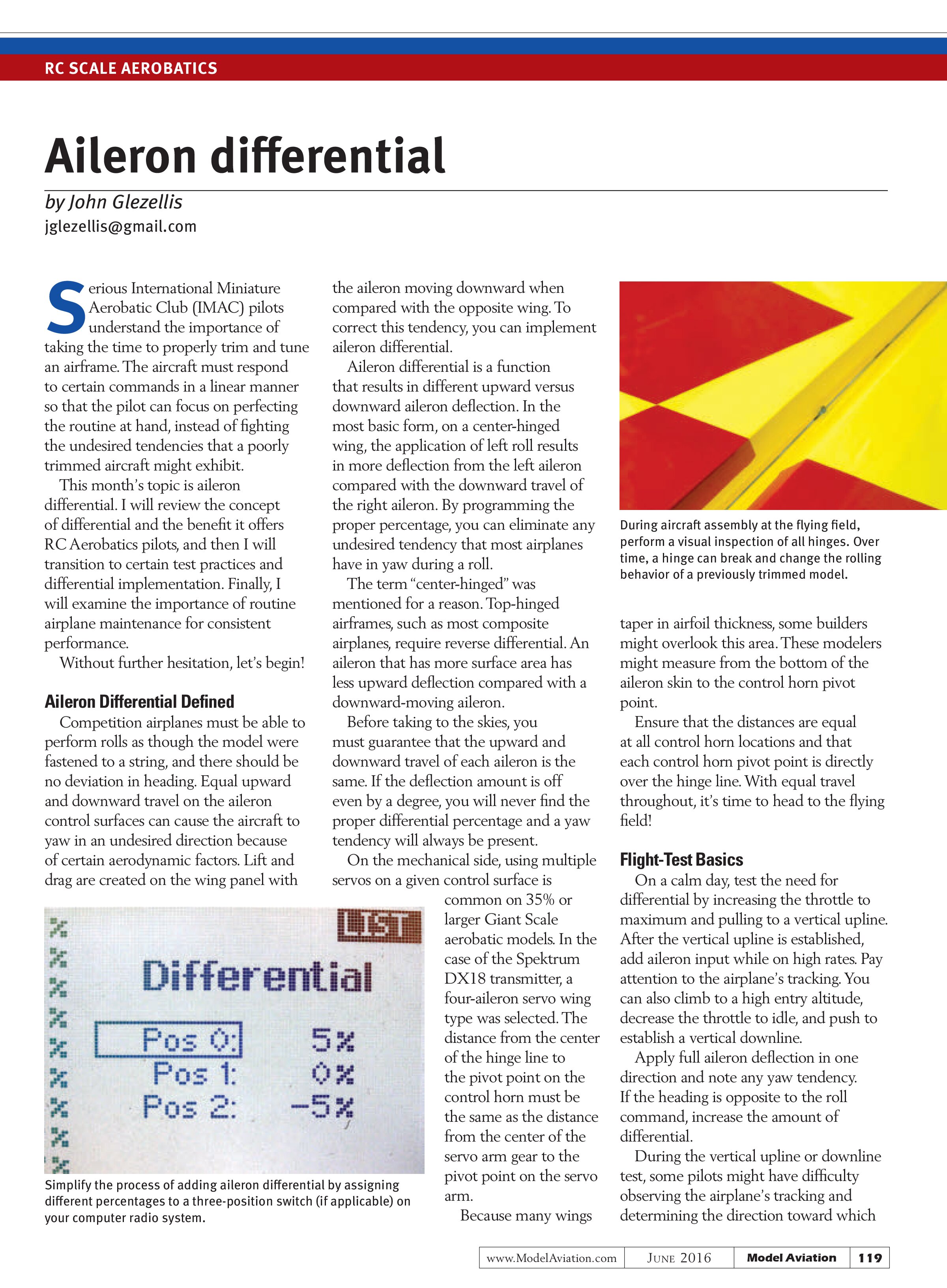
During aircraft assembly at the flying field, perform a visual inspection of all hinges. Over time, a hinge can break and change the rolling behavior of a previously trimmed model.
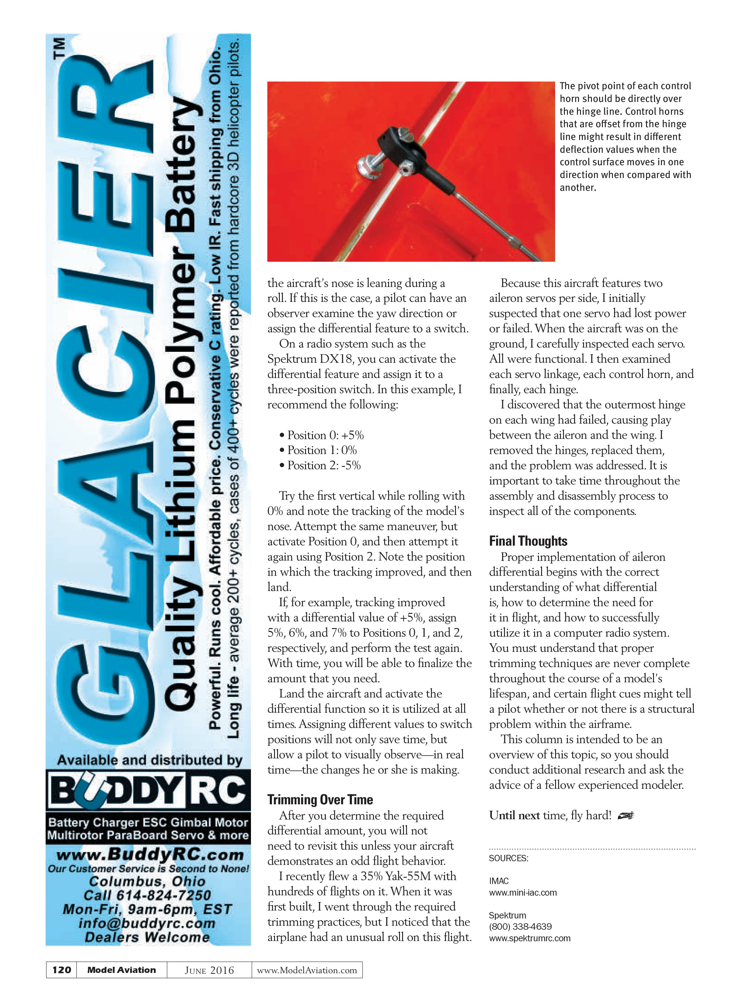
taper in airfoil thickness, some builders might overlook this area. These modelers might measure from the bottom of the aileron skin to the control horn pivot point.
Ensure that the distances are equal at all control horn locations and that each control horn pivot point is directly over the hinge line. With equal travel throughout, it’s time to head to the flying field!
Flight-Test Basics
On a calm day, test the need for differential by increasing the throttle to maximum and pulling to a vertical upline. After the vertical upline is established, add aileron input while on high rates. Pay attention to the airplane’s tracking. You can also climb to a high entry altitude, decrease the throttle to idle, and push to establish a vertical downline.
Apply full aileron deflection in one direction and note any yaw tendency. If the heading is opposite to the roll command, increase the amount of differential.
During the vertical upline or downline test, some pilots might have difficulty observing the airplane’s tracking and determining the direction toward which

the aircraft’s nose is leaning during a roll. If this is the case, a pilot can have an observer examine the yaw direction or assign the differential feature to a switch.
On a radio system such as the Spektrum DX18, you can activate the differential feature and assign it to a three-position switch. In this example, I recommend the following:
- Position 0: +5%
- Position 1: 0%
- Position 2: -5%
Try the first vertical while rolling with 0% and note the tracking of the model’s nose. Attempt the same maneuver, but activate Position 0, and then attempt it again using Position 2. Note the position in which the tracking improved, and then land.
If, for example, tracking improved with a differential value of +5%, assign 5%, 6%, and 7% to Positions 0, 1, and 2, respectively, and perform the test again. With time, you will be able to finalize the amount that you need.
Land the aircraft and activate the differential function so it is utilized at all times. Assigning different values to switch positions will not only save time, but allow a pilot to visually observe—in real time—the changes he or she is making.
Trimming Over Time
After you determine the required differential amount, you will not need to revisit this unless your aircraft demonstrates an odd flight behavior.
I recently flew a 35% Yak-55M with hundreds of flights on it. When it was first built, I went through the required trimming practices, but I noticed that the airplane had an unusual roll on this flight.
Because this aircraft features two aileron servos per side, I initially suspected that one servo had lost power or failed. When the aircraft was on the ground, I carefully inspected each servo. All were functional. I then examined each servo linkage, each control horn, and finally, each hinge.
I discovered that the outermost hinge on each wing had failed, causing play between the aileron and the wing. I removed the hinges, replaced them, and the problem was addressed. It is important to take time throughout the assembly and disassembly process to inspect all of the components.
Final Thoughts
Proper implementation of aileron differential begins with the correct understanding of what differential is, how to determine the need for it in flight, and how to successfully utilize it in a computer radio system. You must understand that proper trimming techniques are never complete throughout the course of a model’s lifespan, and certain flight cues might tell a pilot whether or not there is a structural problem within the airframe.
This column is intended to be an overview of this topic, so you should conduct additional research and ask the advice of a fellow experienced modeler.
Until next time, fly hard!
SOURCES:
IMAC
www.mini-iac.com
Spektrum
(800) 338-4639
www.spektrumrc.com