DGA-3 Pete
by Paul Kohlmann

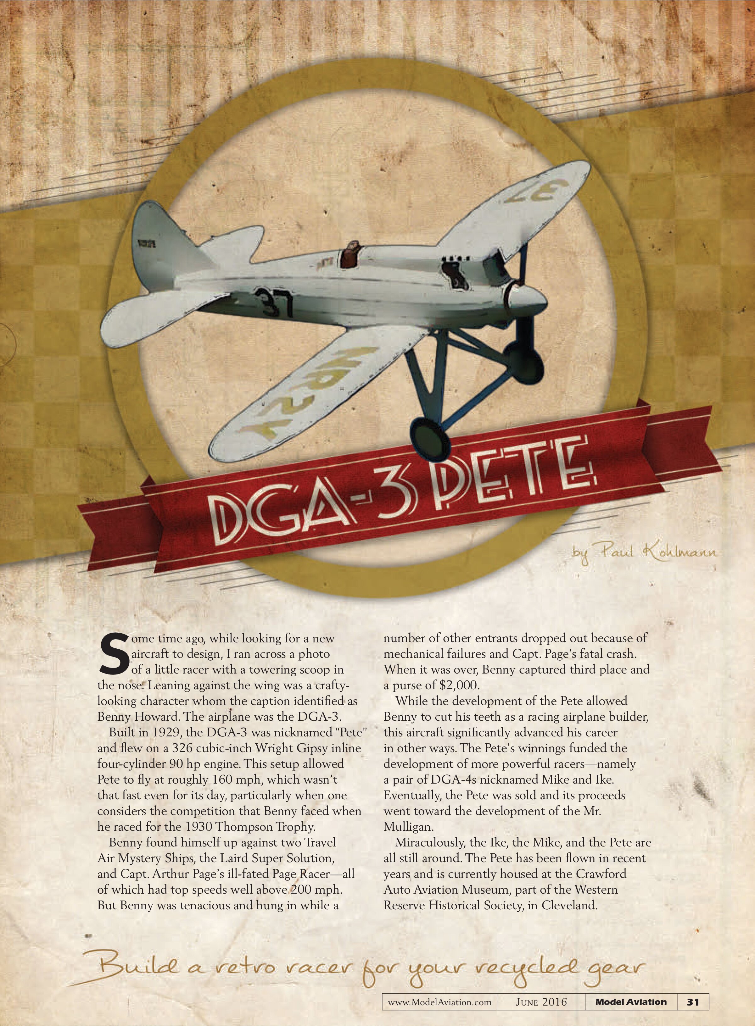
Some time ago, while looking for a new aircraft to design, I ran across a photo of a little racer with a towering scoop in the nose. Leaning against the wing was a crafty-looking character whom the caption identified as Benny Howard. The airplane was the DGA-3.
Built in 1929, the DGA-3 was nicknamed “Pete” and flew on a 326 cubic-inch Wright Gipsy inline four-cylinder 90 hp engine. This setup allowed Pete to fly at roughly 160 mph, which wasn’t that fast even for its day, particularly when one considers the competition that Benny faced when he raced for the 1930 Thompson Trophy.
Benny found himself up against two Travel Air Mystery Ships, the Laird Super Solution, and Capt. Arthur Page’s ill-fated Page Racer—all of which had top speeds well above 200 mph. But Benny was tenacious and hung in while a number of other entrants dropped out because of mechanical failures and Capt. Page’s fatal crash. When it was over, Benny captured third place and a purse of $2,000.
While the development of the Pete allowed Benny to cut his teeth as a racing airplane builder, this aircraft significantly advanced his career in other ways. The Pete’s winnings funded the development of more powerful racers—namely a pair of DGA-4s nicknamed Mike and Ike. Eventually, the Pete was sold and its proceeds went toward the development of the Mr. Mulligan.
Miraculously, the Ike, the Mike, and the Pete are all still around. The Pete has been flown in recent years and is currently housed at the Crawford Auto Aviation Museum, part of the Western Reserve Historical Society, in Cleveland.


Design
The goal of this design was to repurpose an AR6400 “brick” from a worn-out UMX T-28. The brick is a compact little system that integrates a Spektrum receiver, brushed 1S ESC, and two servos into a tiny, 3.9-gram package.
The result is a 20-inch Free Flight-style (FF) airframe with full-house controls that weighs 70 grams. The tiny Pete flies well on the brushed 1S motor, but today there are more powerful bricks with 2S brushless ESCs in similar-size packages. My Pete will be ready for this upgrade as soon I can distract my son’s attention while he’s flying his UMX Beast.
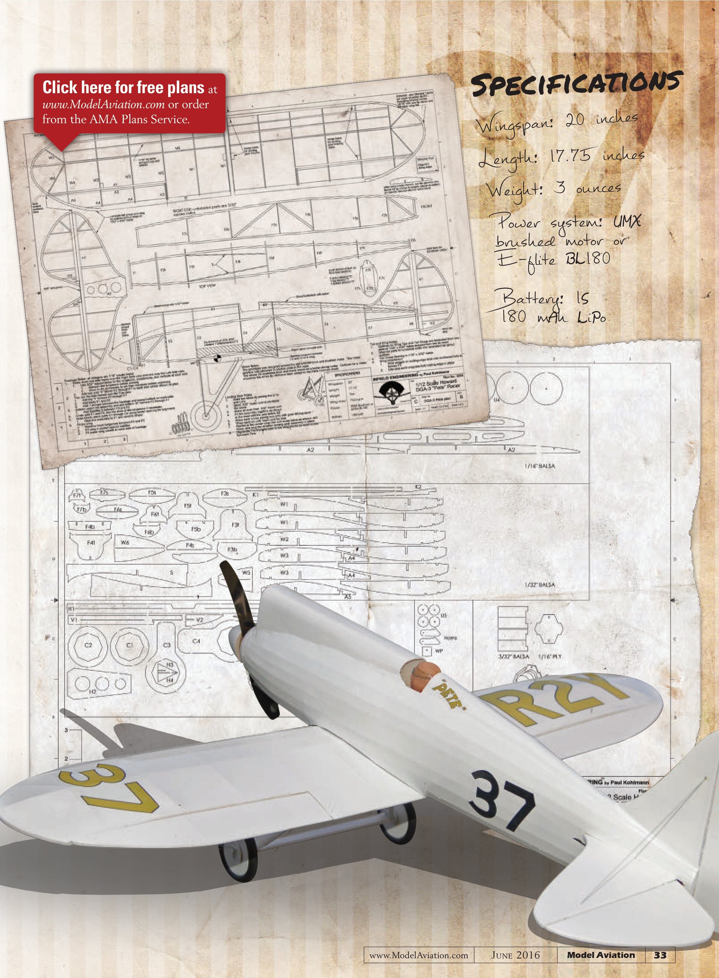
The plans for the Pete have been cleaned up and are offered through Model Aviation as a free download. It’s a simple little project that can be cut by hand. Alternatively, a nice laser-cut kit is available from Manzano Laser Works.
Building Pete
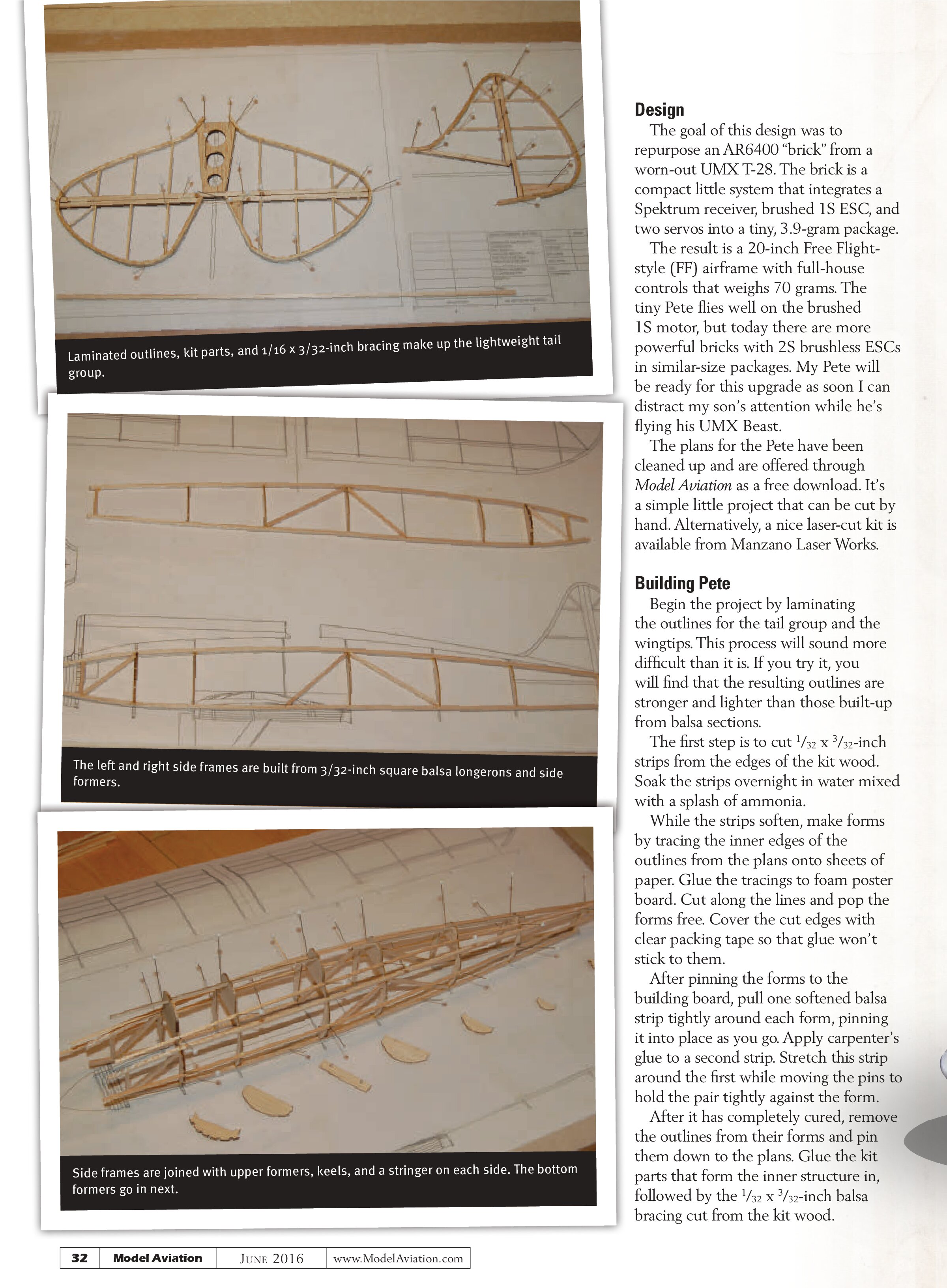
Begin the project by laminating the outlines for the tail group and the wingtips. This process will sound more difficult than it is. If you try it, you will find that the resulting outlines are stronger and lighter than those built-up from balsa sections.
The first step is to cut 1/32 x 3/32-inch strips from the edges of the kit wood. Soak the strips overnight in water mixed with a splash of ammonia.
While the strips soften, make forms by tracing the inner edges of the outlines from the plans onto sheets of paper. Glue the tracings to foam poster board. Cut along the lines and pop the forms free. Cover the cut edges with clear packing tape so that glue won’t stick to them.
After pinning the forms to the building board, pull one softened balsa strip tightly around each form, pinning it into place as you go. Apply carpenter’s glue to a second strip. Stretch this strip around the first while moving the pins to hold the pair tightly against the form.
After it has completely cured, remove the outlines from their forms and pin them down to the plans. Glue the kit parts that form the inner structure in, followed by the 1/32 x 3/32-inch balsa bracing cut from the kit wood.
Specifications
Wingspan: 20 inches
Length: 17.75 inches
Weight: 3 ounces
Power system: UMX brushed motor or E-flite BL180
Battery: 1S 180 mAh LiPo

Split the control surfaces by cutting through the outlines where shown on the plans. Bevel the leading edges (LEs) of the elevators and the rudder to allow ample deflection. Narrow CA hinges work great on these tiny models.
The Fuselage
The fuselage is constructed in the FF style. Two flat side frames are built from ³⁄₃₂-inch square longerons that are spaced by partial formers. After the side frames have cured, pin them over the top view and join them with the top formers. Tie the top formers together with the balsa keels K1 and K2 and a long stringer on each side where the scoop/turtledeck meets the fuselage.
Carefully remove the assembly from the board and add bottom formers F2 through F7. Glue the end formers F1 and F8 into place at each end. Tie F3, F4, and F5 together with the wing saddles S.
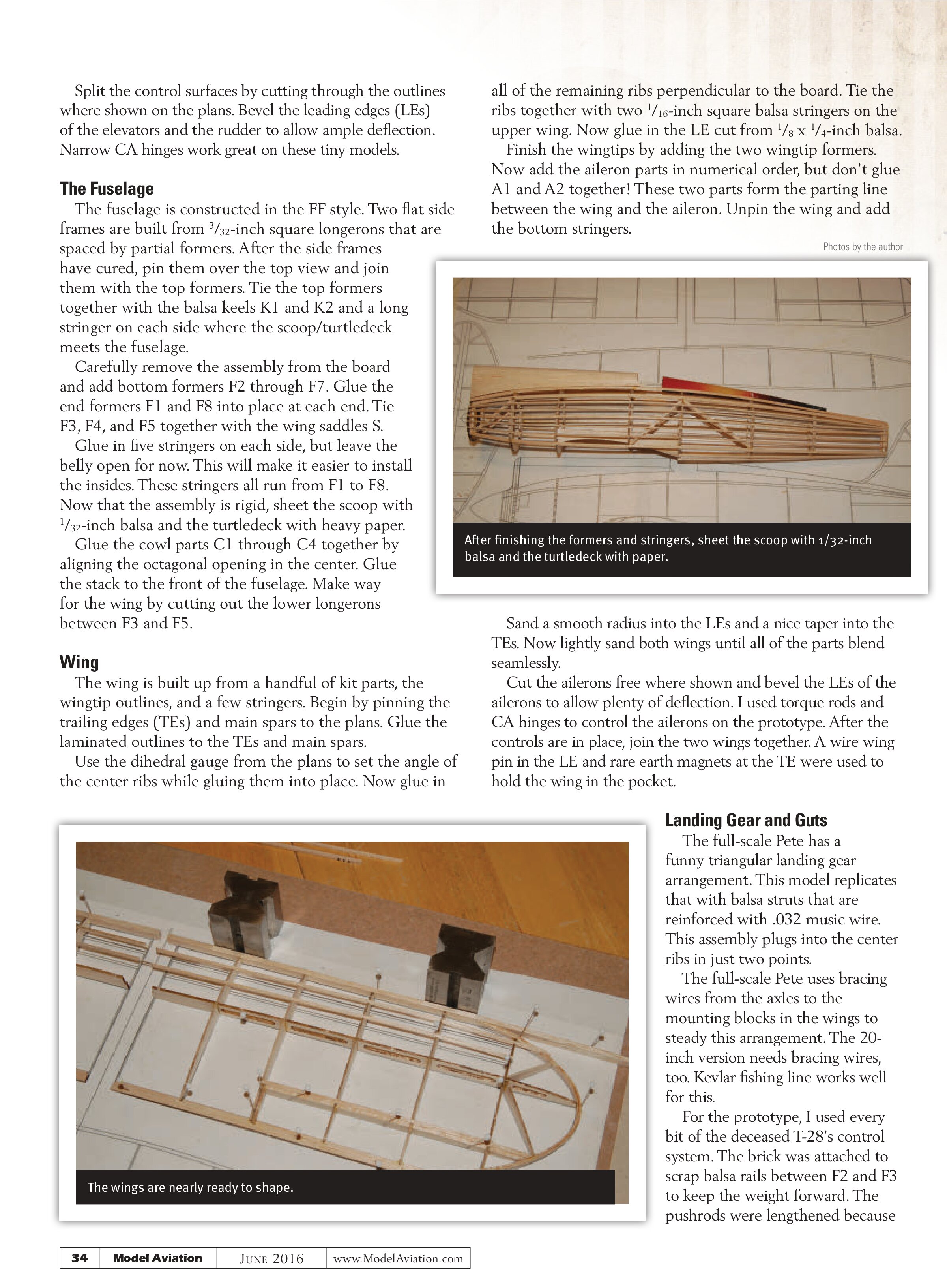
Glue in five stringers on each side, but leave the belly open for now. This will make it easier to install the insides. These stringers all run from F1 to F8. Now that the assembly is rigid, sheet the scoop with ¹⁄₃₂-inch balsa and the turtledeck with heavy paper.
Glue the cowl parts C1 through C4 together by aligning the octagonal opening in the center. Glue the stack to the front of the fuselage. Make way for the wing by cutting out the lower longerons between F3 and F5.
Wing
The wing is built up from a handful of kit parts, the wingtip outlines, and a few stringers. Begin by pinning the trailing edges (TEs) and main spars to the plans. Glue the laminated outlines to the TEs and main spars.
Use the dihedral gauge from the plans to set the angle of the center ribs while gluing them into place. Now glue in
all of the remaining ribs perpendicular to the board. Tie the ribs together with two ¹⁄₁₆-inch square balsa stringers on the upper wing. Now glue in the LE cut from ⅛ x ¼-inch balsa. Finish the wingtips by adding the two wingtip formers. Now add the aileron parts in numerical order, but don’t glue A1 and A2 together! These two parts form the parting line between the wing and the aileron. Unpin the wing and add the bottom stringers.

Sand a smooth radius into the LEs and a nice taper into the TEs. Now lightly sand both wings until all of the parts blend seamlessly.
Cut the ailerons free where shown and bevel the LEs of the ailerons to allow plenty of deflection. I used torque rods and CA hinges to control the ailerons on the prototype. After the controls are in place, join the two wings together. A wire wing pin in the LE and rare earth magnets at the TE were used to hold the wing in the pocket.

Landing Gear and Guts
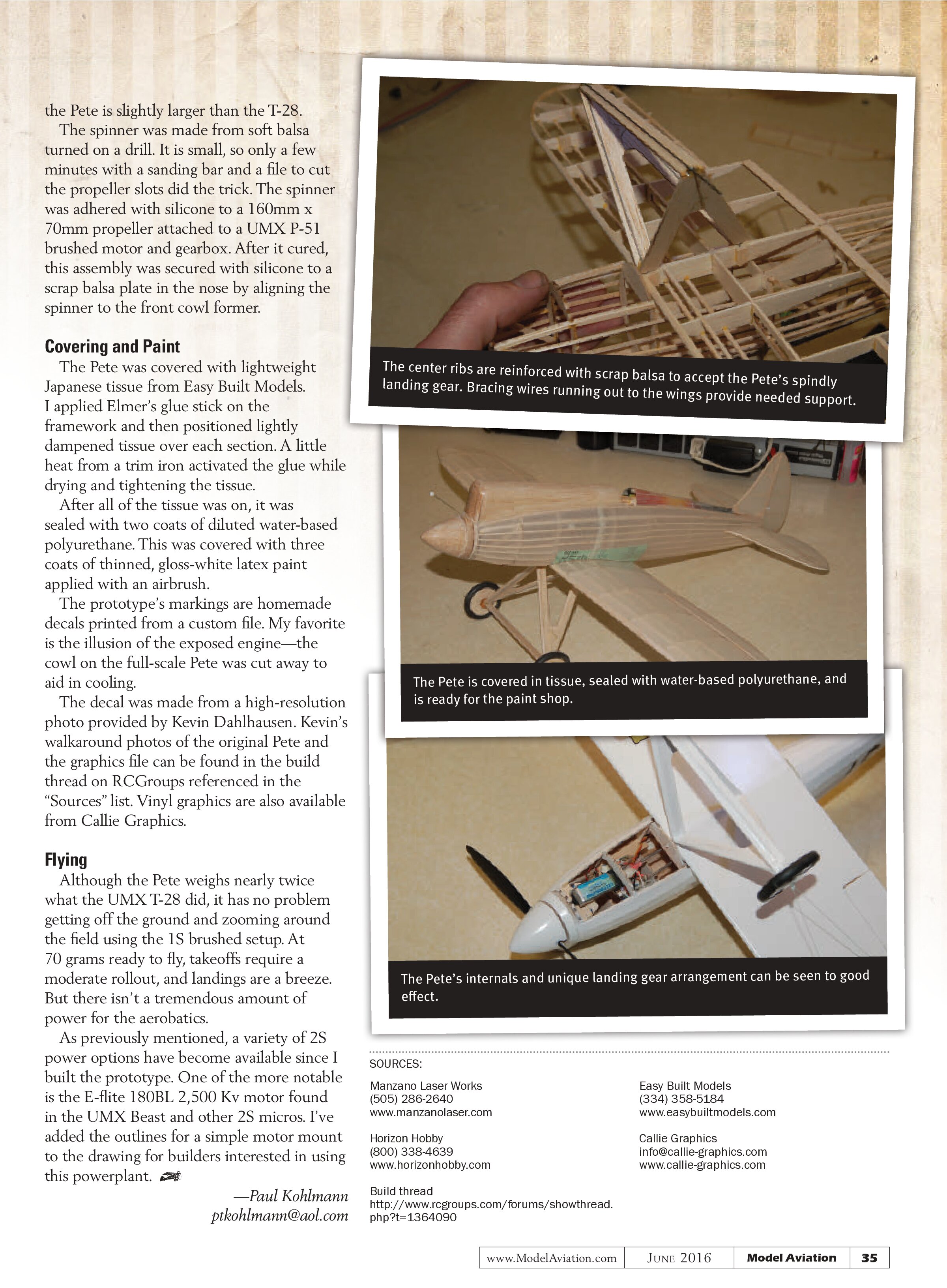
The full-scale Pete has a funny triangular landing gear arrangement. This model replicates that with balsa struts that are reinforced with .032 music wire. This assembly plugs into the center ribs in just two points.
The full-scale Pete uses bracing wires from the axles to the mounting blocks in the wings to steady this arrangement. The 20-inch version needs bracing wires, too. Kevlar fishing line works well for this.
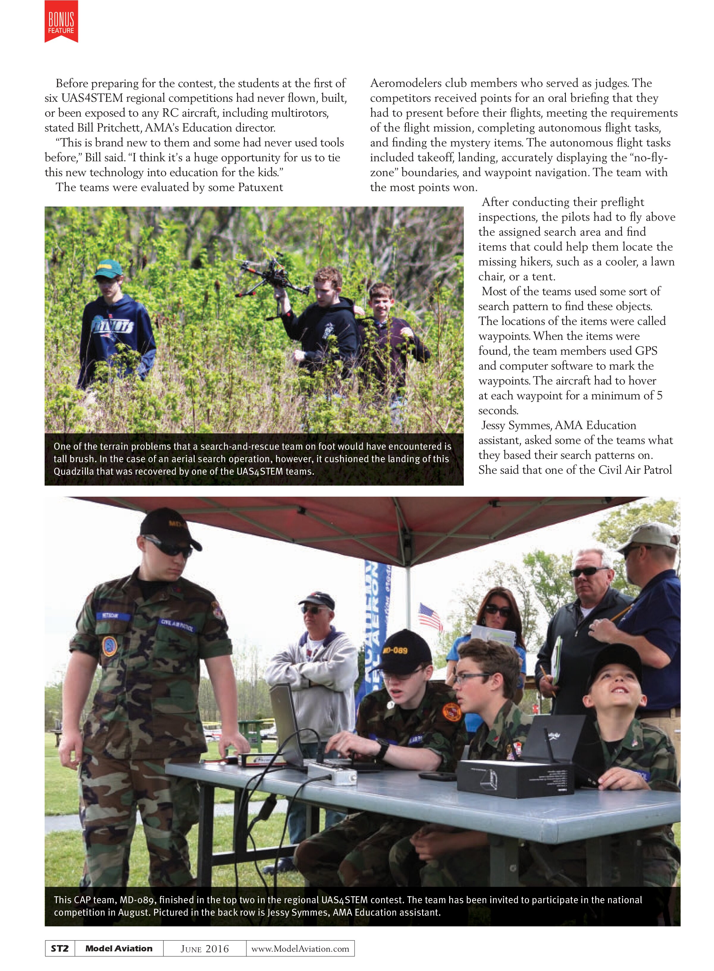
For the prototype, I used every bit of the deceased T-28’s control system. The brick was attached to scrap balsa rails between F2 and F3 to keep the weight forward. The pushrods were lengthened because the Pete is slightly larger than the T-28.
The spinner was made from soft balsa turned on a drill. It is small, so only a few minutes with a sanding bar and a file to cut the propeller slots did the trick. The spinner was adhered with silicone to a 160mm x 70mm propeller attached to a UMX P-51 brushed motor and gearbox. After it cured, this assembly was secured with silicone to a scrap balsa plate in the nose by aligning the spinner to the front cowl former.
Covering and Paint
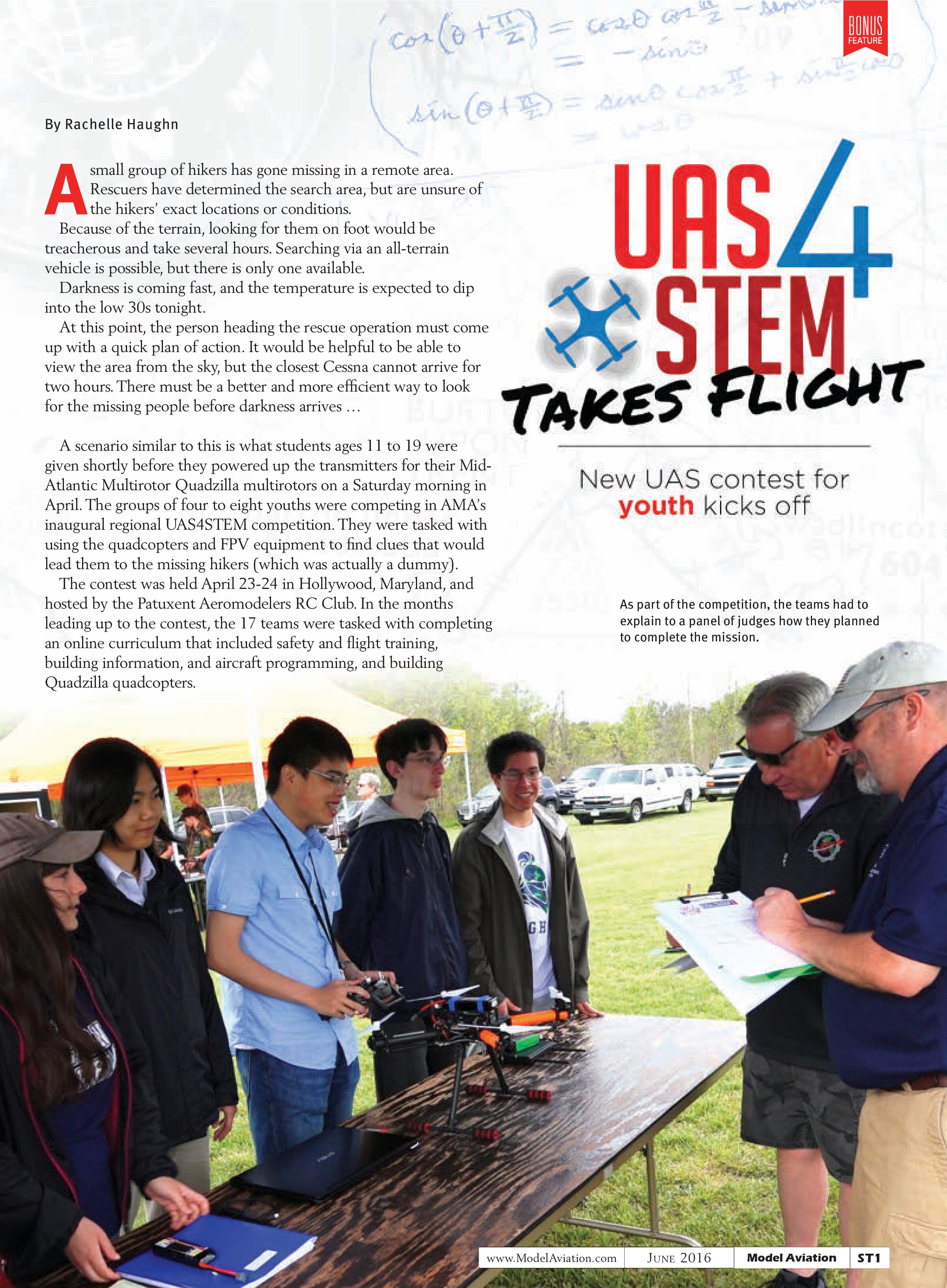
The Pete was covered with lightweight Japanese tissue from Easy Built Models. I applied Elmer’s glue stick on the framework and then positioned lightly dampened tissue over each section. A little heat from a trim iron activated the glue while drying and tightening the tissue.
After all of the tissue was on, it was sealed with two coats of diluted water-based polyurethane. This was covered with three coats of thinned, gloss-white latex paint applied with an airbrush.
The prototype’s markings are homemade decals printed from a custom file. My favorite is the illusion of the exposed engine—the cowl on the full-scale Pete was cut away to aid in cooling.
The decal was made from a high-resolution photo provided by Kevin Dahlhausen. Kevin’s walkaround photos of the original Pete and the graphics file can be found in the build thread on RCGroups referenced in the “Sources” list. Vinyl graphics are also available from Callie Graphics.
Flying
Although the Pete weighs nearly twice what the UMX T-28 did, it has no problem getting off the ground and zooming around the field using the 1S brushed setup. At 70 grams ready to fly, takeoffs require a moderate rollout, and landings are a breeze. But there isn’t a tremendous amount of power for the aerobatics.
As previously mentioned, a variety of 2S power options have become available since I built the prototype. One of the more notable is the E-flite 180BL 2,500 Kv motor found in the UMX Beast and other 2S micros. I’ve added the outlines for a simple motor mount to the drawing for builders interested in using this powerplant.
—Paul Kohlmann
ptkohlmann@aol.com


SOURCES:
Manzano Laser Works
(505) 286-2640
www.manzanolaser.com
Horizon Hobby
(800) 338-4639
www.horizonhobby.com
Build thread
http://www.rcgroups.com/forums/showthread.php?t=1364090
Easy Built Models
(334) 358-5184
www.easybuiltmodels.com
Callie Graphics
info@callie-graphics.com
www.callie-graphics.com
By Rachelle Haugh
A small group of hikers has gone missing in a remote area. Rescuers have determined the search area, but are unsure of the hikers’ exact locations or conditions. Because of the terrain, looking for them on foot would be treacherous and take several hours. Searching via an all-terrain vehicle is possible, but there is only one available.
Darkness is coming fast, and the temperature is expected to dip into the low 30s tonight.
At this point, the person heading the rescue operation must come up with a quick plan of action. It would be helpful to be able to view the area from the sky, but the closest Cessna cannot arrive for two hours. There must be a better and more efficient way to look for the missing people before darkness arrives …
A scenario similar to this is what students ages 11 to 19 were given shortly before they powered up the transmitters for their Mid-Atlantic Multirotor Quadzilla multirotors on a Saturday morning in April. The groups of four to eight youths were competing in AMA’s inaugural regional UAS4STEM competition. They were tasked with using the quadcopters and FPV equipment to find clues that would lead them to the missing hikers (which was actually a dummy).
The contest was held April 23-24 in Hollywood, Maryland, and hosted by the Patuxent Aeromodelers RC Club. In the months leading up to the contest, the 17 teams were tasked with completing an online curriculum that included safety and flight training, building information, and aircraft programming, and building Quadzilla quadcopters.

Before preparing for the contest, the students at the first of six UAS4STEM regional competitions had never flown, built, or been exposed to any RC aircraft, including multirotors, stated Bill Pritchett, AMA’s Education director.
“This is brand new to them and some had never used tools before,” Bill said. “I think it’s a huge opportunity for us to tie this new technology into education for the kids.”
The teams were evaluated by some Patuxent Aeromodelers club members who served as judges. The competitors received points for an oral briefing that they had to present before their flights, meeting the requirements of the flight mission, completing autonomous flight tasks, and finding the mystery items. The autonomous flight tasks included takeoff, landing, accurately displaying the “no-fly-zone” boundaries, and waypoint navigation. The team with the most points won.

After conducting their preflight inspections, the pilots had to fly above the assigned search area and find items that could help them locate the missing hikers, such as a cooler, a lawn chair, or a tent.
Most of the teams used some sort of search pattern to find these objects. The locations of the items were called waypoints. When the items were found, the team members used GPS and computer software to mark the waypoints. The aircraft had to hover at each waypoint for a minimum of 5 seconds.
Jessy Symmes, AMA Education assistant, asked some of the teams what they based their search patterns on. She said that one of the Civil Air Patrol