Fuel systems and brakes
by Jim Hiller
jetmodeler@earthlink.net
To pick up where my March 2016 column left off, let’s continue setting up a new turbine model for a test flight and systems check, starting with the fuel system.
I use the term system because of the complexity of a modern jet installation. My new model has two composite-constructed saddle tanks, each with a capacity of approximately 100 ounces. They will be set up to feed a center 24-ounce fuel tank, then the Bob Violett Models (BVM) Ultimate Air Trap (UAT). I call this my fuel tank system.
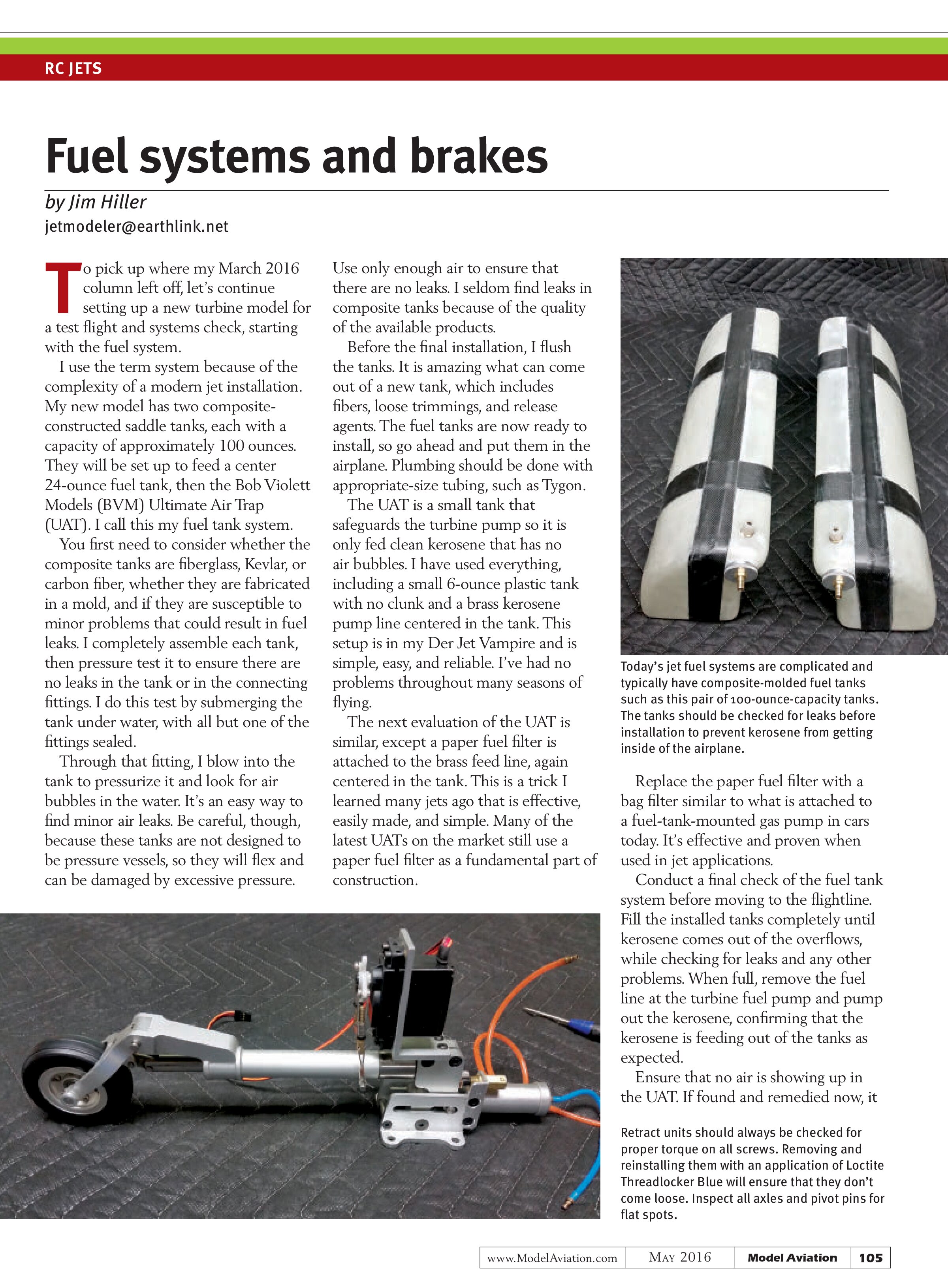
You first need to consider whether the composite tanks are fiberglass, Kevlar, or carbon fiber, whether they are fabricated in a mold, and if they are susceptible to minor problems that could result in fuel leaks. I completely assemble each tank, then pressure test it to ensure there are no leaks in the tank or in the connecting fittings. I do this test by submerging the tank under water, with all but one of the fittings sealed.
Through that fitting, I blow into the tank to pressurize it and look for air bubbles in the water. It’s an easy way to find minor air leaks. Be careful, though, because these tanks are not designed to be pressure vessels, so they will flex and can be damaged by excessive pressure.
Use only enough air to ensure that there are no leaks. I seldom find leaks in composite tanks because of the quality of the available products.
Before the final installation, I flush the tanks. It is amazing what can come out of a new tank, which includes fibers, loose trimmings, and release agents. The fuel tanks are now ready to install, so go ahead and put them in the airplane. Plumbing should be done with appropriate-size tubing, such as Tygon.
The UAT is a small tank that safeguards the turbine pump so it is only fed clean kerosene that has no air bubbles. I have used everything, including a small 6-ounce plastic tank with no clunk and a brass kerosene pump line centered in the tank. This setup is in my Der Jet Vampire and is simple, easy, and reliable. I’ve had no problems throughout many seasons of flying.
The next evaluation of the UAT is similar, except a paper fuel filter is attached to the brass feed line, again centered in the tank. This is a trick I learned many jets ago that is effective, easily made, and simple. Many of the latest UATs on the market still use a paper fuel filter as a fundamental part of construction.

Today’s jet fuel systems are complicated and typically have composite-molded fuel tanks such as this pair of 100-ounce-capacity tanks. The tanks should be checked for leaks before installation to prevent kerosene from getting inside of the airplane.
Replace the paper fuel filter with a bag filter similar to what is attached to a fuel-tank-mounted gas pump in cars today. It’s effective and proven when used in jet applications.
Conduct a final check of the fuel tank system before moving to the flightline. Fill the installed tanks completely until kerosene comes out of the overflows, while checking for leaks and any other problems. When full, remove the fuel line at the turbine fuel pump and pump out the kerosene, confirming that the kerosene is feeding out of the tanks as expected.
Ensure that no air is showing up in the UAT. If found and remedied now, it

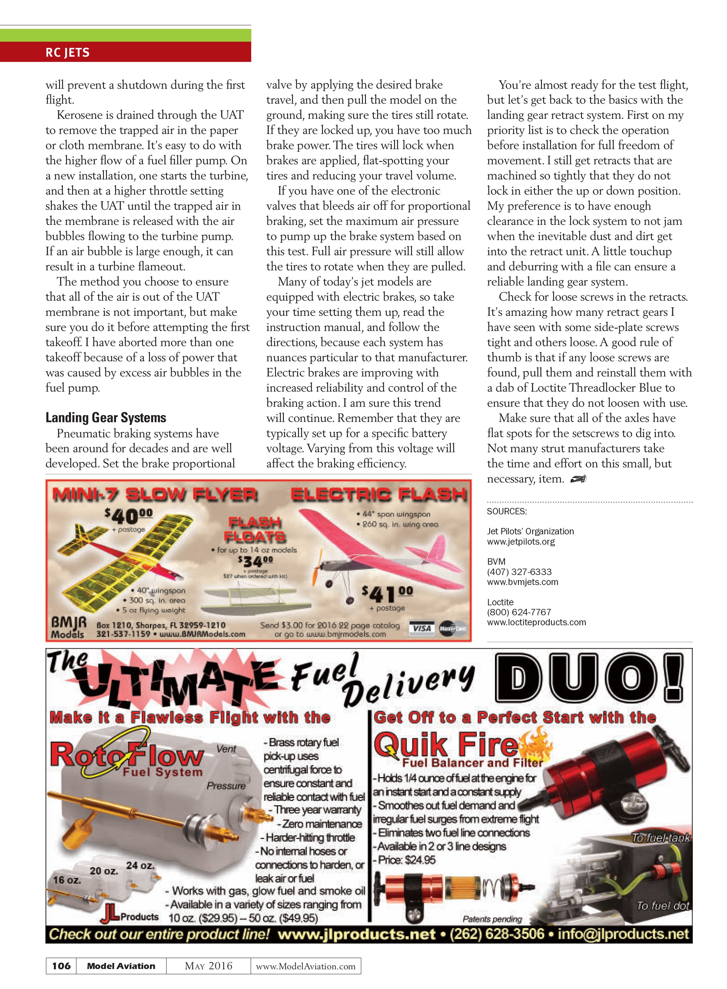
Retract units should always be checked for proper torque on all screws. Removing and reinstalling them with an application of Loctite Threadlocker Blue will ensure that they don’t come loose. Inspect all axles and pivot pins for flat spots.
will prevent a shutdown during the first flight.
Kerosene is drained through the UAT to remove the trapped air in the paper or cloth membrane. It’s easy to do with the higher flow of a fuel filler pump. On a new installation, one starts the turbine, and then at a higher throttle setting shakes the UAT until the trapped air in the membrane is released with the air bubbles flowing to the turbine pump. If an air bubble is large enough, it can result in a turbine flameout.
The method you choose to ensure that all of the air is out of the UAT membrane is not important, but make sure you do it before attempting the first takeoff. I have aborted more than one takeoff because of a loss of power that was caused by excess air bubbles in the fuel pump.
Landing Gear Systems
Pneumatic braking systems have been around for decades and are well developed. Set the brake proportional valve by applying the desired brake travel, and then pull the model on the ground, making sure the tires still rotate. If they are locked up, you have too much brake power. The tires will lock when brakes are applied, flat-spotting your tires and reducing your travel volume.
If you have one of the electronic valves that bleeds air off for proportional braking, set the maximum air pressure to pump up the brake system based on this test. Full air pressure will still allow the tires to rotate when they are pulled.
Many of today’s jet models are equipped with electric brakes, so take your time setting them up, read the instruction manual, and follow the directions, because each system has nuances particular to that manufacturer. Electric brakes are improving with increased reliability and control of the braking action. I am sure this trend will continue. Remember that they are typically set up for a specific battery voltage. Varying from this voltage will affect the braking efficiency.
You’re almost ready for the test flight, but let’s get back to the basics with the landing gear retract system. First on my priority list is to check the operation before installation for full freedom of movement. I still get retracts that are machined so tightly that they do not lock in either the up or down position. My preference is to have enough clearance in the lock system to not jam when the inevitable dust and dirt get into the retract unit. A little touchup and deburring with a file can ensure a reliable landing gear system.
Check for loose screws in the retracts. It’s amazing how many retract gears I have seen with some side-plate screws tight and others loose. A good rule of thumb is that if any loose screws are found, pull them and reinstall them with a dab of Loctite Threadlocker Blue to ensure that they do not loosen with use.
Make sure that all of the axles have flat spots for the setscrews to dig into. Not many strut manufacturers take the time and effort on this small, but necessary, item.
SOURCES:
Jet Pilots’ Organization
www.jetpilots.org
BVM
(407) 327-6333
www.bvmjets.com
Loctite
(800) 624-7767
www.loctiteproducts.com