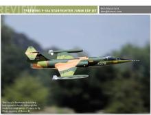
Freewing F-104 Starfighter 70Mm Edf Jet
Don Slusarczyk
don@donsrc.com

You don’t have to be an ace to pilot this jet
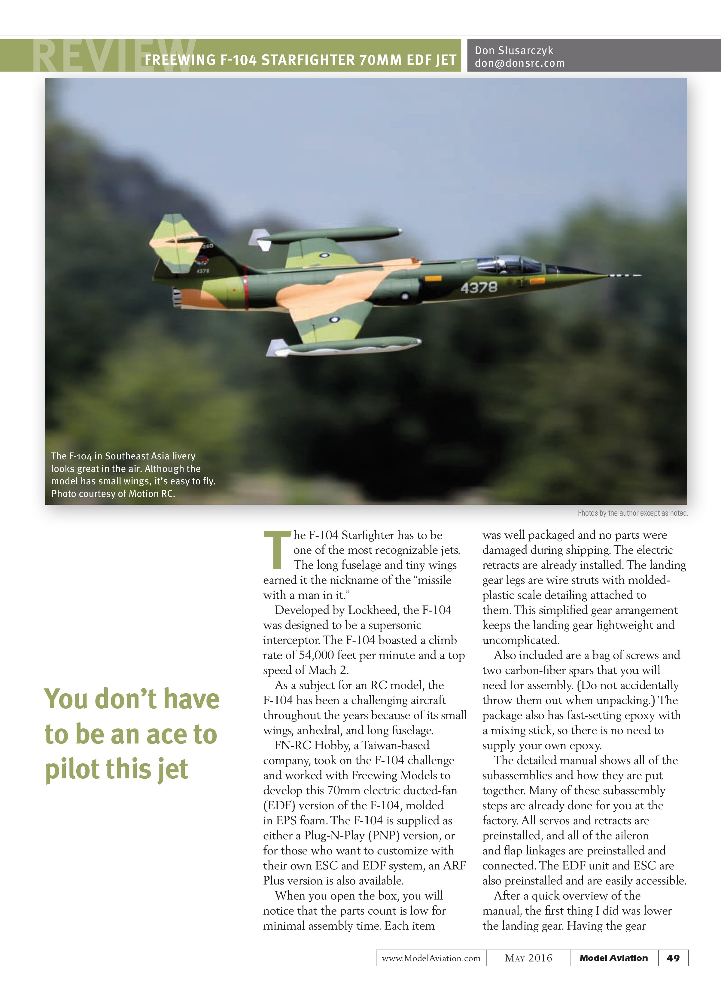
The F-104 Starfighter has to be one of the most recognizable jets. The long fuselage and tiny wings earned it the nickname of the “missile with a man in it.”
Developed by Lockheed, the F-104 was designed to be a supersonic interceptor. The F-104 boasted a climb rate of 54,000 feet per minute and a top speed of Mach 2.
As a subject for an RC model, the F-104 has been a challenging aircraft throughout the years because of its small wings, anhedral, and long fuselage.
FN-RC Hobby, a Taiwan-based company, took on the F-104 challenge and worked with Freewing Models to develop this 70mm electric ducted-fan (EDF) version of the F-104, molded in EPS foam. The F-104 is supplied as either a Plug-N-Play (PNP) version, or for those who want to customize with their own ESC and EDF system, an ARF Plus version is also available.
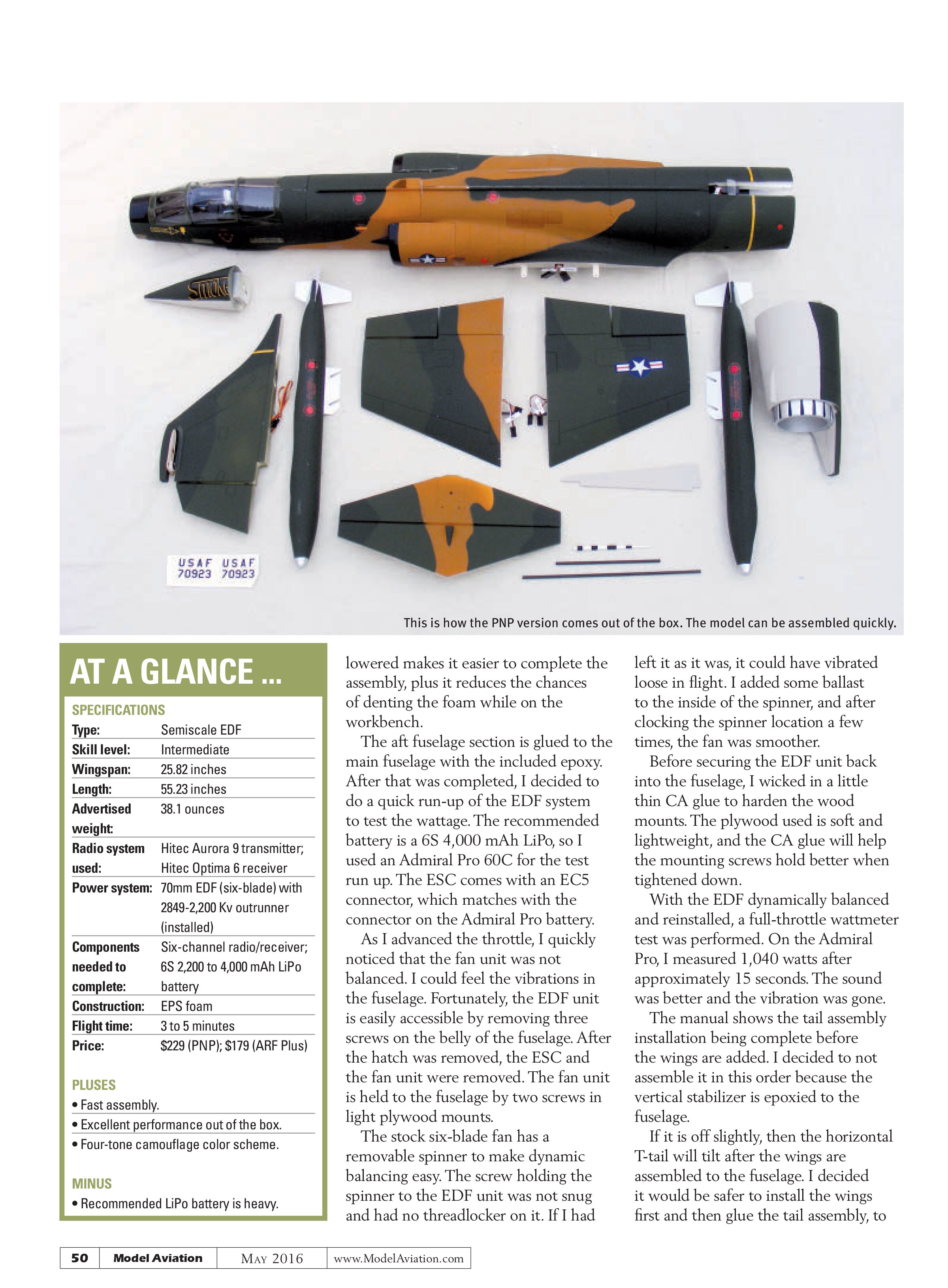
When you open the box, you will notice that the parts count is low for minimal assembly time. Each item was well packaged and no parts were damaged during shipping. The electric retracts are already installed. The landing gear legs are wire struts with molded-plastic scale detailing attached to them. This simplified gear arrangement keeps the landing gear lightweight and uncomplicated.
Also included are a bag of screws and two carbon-fiber spars that you will need for assembly. (Do not accidentally throw them out when unpacking.) The package also has fast-setting epoxy with a mixing stick, so there is no need to supply your own epoxy.
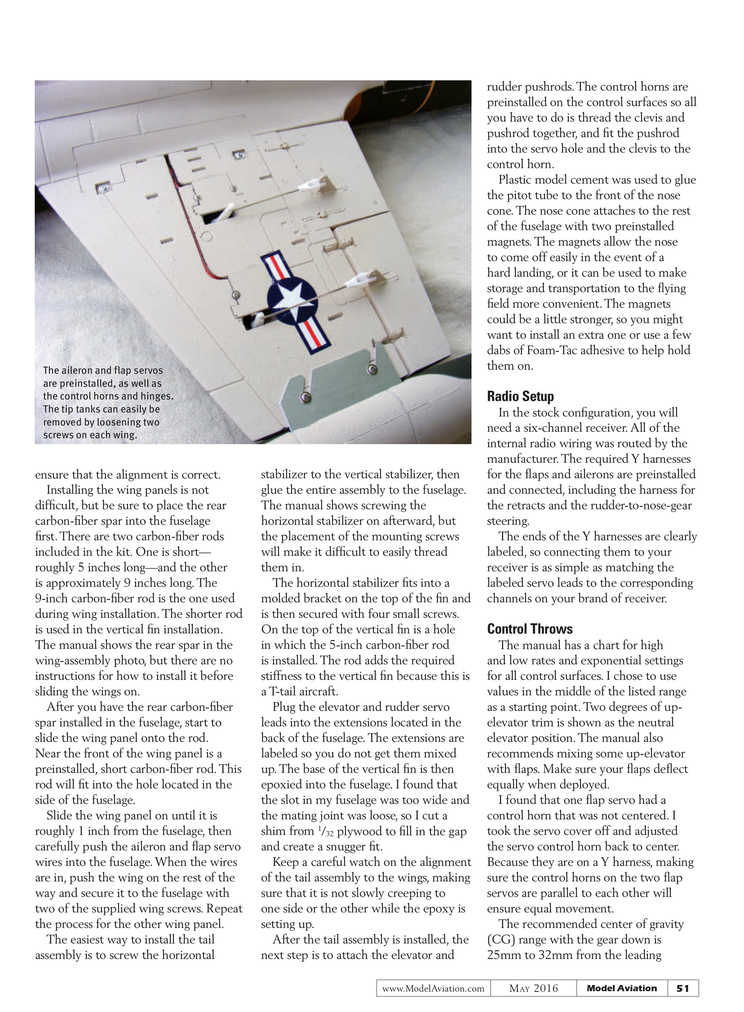
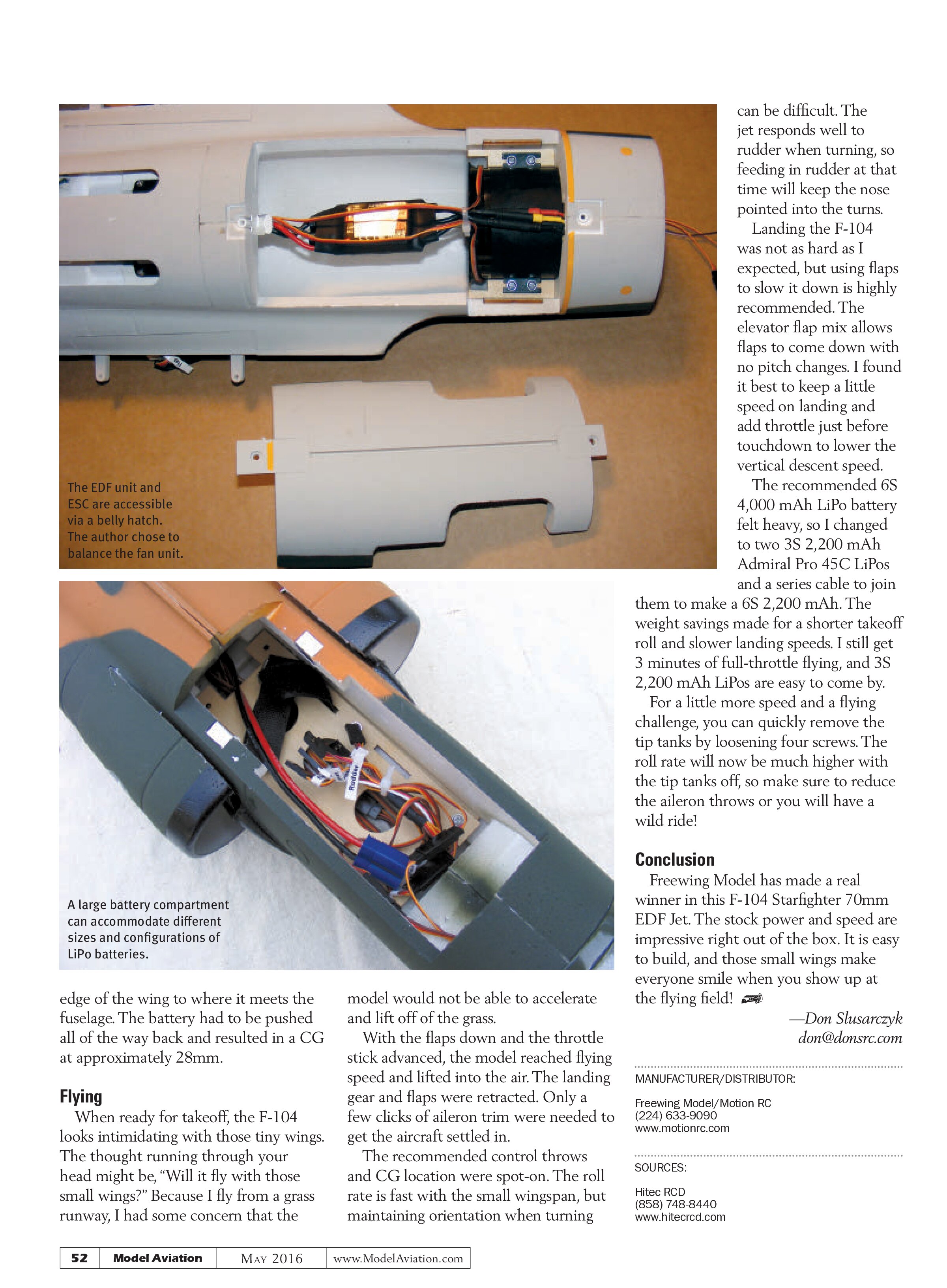
The detailed manual shows all of the subassemblies and how they are put together. Many of these subassembly steps are already done for you at the factory. All servos and retracts are preinstalled, and all of the aileron and flap linkages are preinstalled and connected. The EDF unit and ESC are also preinstalled and are easily accessible.
After a quick overview of the manual, the first thing I did was lower the landing gear. Having the gear

AT A GLANCE ...
SPECIFICATIONS
Type: Semiscale EDF
Skill level: Intermediate
Wingspan: 25.82 inches
Length: 55.23 inches
Advertised weight: 38.1 ounces
Radio system used: Hitec Aurora 9 transmitter; Hitec Optima 6 receiver
Power system: 70mm EDF (six-blade) with 2849-2,200 Kv outrunner (installed)
Components needed to complete: Six-channel radio/receiver; 6S 2,200 to 4,000 mAh LiPo battery
Construction: EPS foam
Flight time: 3 to 5 minutes
Price: $229 (PNP); $179 (ARF Plus)
PLUSES
- Fast assembly.
- Excellent performance out of the box.
- Four-tone camouflage color scheme.
MINUS
- Recommended LiPo battery is heavy.
lowered makes it easier to complete the assembly, plus it reduces the chances of denting the foam while on the workbench.
The aft fuselage section is glued to the main fuselage with the included epoxy. After that was completed, I decided to do a quick run-up of the EDF system to test the wattage. The recommended battery is a 6S 4,000 mAh LiPo, so I used an Admiral Pro 60C for the test run up. The ESC comes with an EC5 connector, which matches with the connector on the Admiral Pro battery.
As I advanced the throttle, I quickly noticed that the fan unit was not balanced. I could feel the vibrations in the fuselage. Fortunately, the EDF unit is easily accessible by removing three screws on the belly of the fuselage. After the hatch was removed, the ESC and the fan unit were removed. The fan unit is held to the fuselage by two screws in light plywood mounts.
The stock six-blade fan has a removable spinner to make dynamic balancing easy. The screw holding the spinner to the EDF unit was not snug and had no threadlocker on it. If I had left it as it was, it could have vibrated loose in flight. I added some ballast to the inside of the spinner, and after clocking the spinner location a few times, the fan was smoother.
Before securing the EDF unit back into the fuselage, I wicked in a little thin CA glue to harden the wood mounts. The plywood used is soft and lightweight, and the CA glue will help the mounting screws hold better when tightened down.
With the EDF dynamically balanced and reinstalled, a full-throttle wattmeter test was performed. On the Admiral Pro, I measured 1,040 watts after approximately 15 seconds. The sound was better and the vibration was gone.
The manual shows the tail assembly installation being complete before the wings are added. I decided to not assemble it in this order because the vertical stabilizer is epoxied to the fuselage.
If it is off slightly, then the horizontal T-tail will tilt after the wings are assembled to the fuselage. I decided it would be safer to install the wings first and then glue the tail assembly, to ensure that the alignment is correct.

Installing the wing panels is not difficult, but be sure to place the rear carbon-fiber spar into the fuselage first. There are two carbon-fiber rods included in the kit. One is short—roughly 5 inches long—and the other is approximately 9 inches long. The 9-inch carbon-fiber rod is the one used during wing installation. The shorter rod is used in the vertical fin installation. The manual shows the rear spar in the wing-assembly photo, but there are no instructions for how to install it before sliding the wings on.
After you have the rear carbon-fiber spar installed in the fuselage, start to slide the wing panel onto the rod. Near the front of the wing panel is a preinstalled, short carbon-fiber rod. This rod will fit into the hole located in the side of the fuselage.
Slide the wing panel on until it is roughly 1 inch from the fuselage, then carefully push the aileron and flap servo wires into the fuselage. When the wires are in, push the wing on the rest of the way and secure it to the fuselage with two of the supplied wing screws. Repeat the process for the other wing panel.
The easiest way to install the tail assembly is to screw the horizontal stabilizer to the vertical stabilizer, then glue the entire assembly to the fuselage. The manual shows screwing the horizontal stabilizer on afterward, but the placement of the mounting screws will make it difficult to easily thread them in.
The horizontal stabilizer fits into a molded bracket on the top of the fin and is then secured with four small screws. On the top of the vertical fin is a hole in which the 5-inch carbon-fiber rod is installed. The rod adds the required stiffness to the vertical fin because this is a T-tail aircraft.
Plug the elevator and rudder servo leads into the extensions located in the back of the fuselage. The extensions are labeled so you do not get them mixed up. The base of the vertical fin is then epoxied into the fuselage. I found that the slot in my fuselage was too wide and the mating joint was loose, so I cut a shim from 1/32 plywood to fill in the gap and create a snugger fit.
Keep a careful watch on the alignment of the tail assembly to the wings, making sure that it is not slowly creeping to one side or the other while the epoxy is setting up.
After the tail assembly is installed, the next step is to attach the elevator and rudder pushrods. The control horns are preinstalled on the control surfaces so all you have to do is thread the clevis and pushrod together, and fit the pushrod into the servo hole and the clevis to the control horn.
Plastic model cement was used to glue the pitot tube to the front of the nose cone. The nose cone attaches to the rest of the fuselage with two preinstalled magnets. The magnets allow the nose to come off easily in the event of a hard landing, or it can be used to make storage and transportation to the flying field more convenient. The magnets could be a little stronger, so you might want to install an extra one or use a few dabs of Foam-Tac adhesive to help hold them on.
Radio Setup
In the stock configuration, you will need a six-channel receiver. All of the internal radio wiring was routed by the manufacturer. The required Y harnesses for the flaps and ailerons are preinstalled and connected, including the harness for the retracts and the rudder-to-nose-gear steering.
The ends of the Y harnesses are clearly labeled, so connecting them to your receiver is as simple as matching the labeled servo leads to the corresponding channels on your brand of receiver.
Control Throws
The manual has a chart for high and low rates and exponential settings for all control surfaces. I chose to use values in the middle of the listed range as a starting point. Two degrees of up-elevator trim is shown as the neutral elevator position. The manual also recommends mixing some up-elevator with flaps. Make sure your flaps deflect equally when deployed.
I found that one flap servo had a control horn that was not centered. I took the servo cover off and adjusted the servo control horn back to center. Because they are on a Y harness, making sure the control horns on the two flap servos are parallel to each other will ensure equal movement.
The recommended center of gravity (CG) range with the gear down is 25mm to 32mm from the leading


edge of the wing to where it meets the fuselage. The battery had to be pushed all of the way back and resulted in a CG at approximately 28mm.
Flying
When ready for takeoff, the F-104 looks intimidating with those tiny wings. The thought running through your head might be, “Will it fly with those small wings?” Because I fly from a grass runway, I had some concern that the model would not be able to accelerate and lift off of the grass.
With the flaps down and the throttle stick advanced, the model reached flying speed and lifted into the air. The landing gear and flaps were retracted. Only a few clicks of aileron trim were needed to get the aircraft settled in.
The recommended control throws and CG location were spot-on. The roll rate is fast with the small wingspan, but maintaining orientation when turning can be difficult. The jet responds well to rudder when turning, so feeding in rudder at that time will keep the nose pointed into the turns.
Landing the F-104 was not as hard as I expected, but using flaps to slow it down is highly recommended. The elevator flap mix allows flaps to come down with no pitch changes. I found it best to keep a little speed on landing and add throttle just before touchdown to lower the vertical descent speed.
The recommended 6S 4,000 mAh LiPo battery felt heavy, so I changed to two 3S 2,200 mAh Admiral Pro 45C LiPos and a series cable to join them to make a 6S 2,200 mAh. The weight savings made for a shorter takeoff roll and slower landing speeds. I still get 3 minutes of full-throttle flying, and 3S 2,200 mAh LiPos are easy to come by.
For a little more speed and a flying challenge, you can quickly remove the tip tanks by loosening four screws. The roll rate will now be much higher with the tip tanks off, so make sure to reduce the aileron throws or you will have a wild ride!
Conclusion
Freewing Model has made a real winner in this F-104 Starfighter 70mm EDF Jet. The stock power and speed are impressive right out of the box. It is easy to build, and those small wings make everyone smile when you show up at the flying field!
—Don Slusarczyk
don@donsrc.com
MANUFACTURER/DISTRIBUTOR:
Freewing Model/Motion RC
(224) 633-9090
www.motionrc.com
SOURCES:
Hitec RCD
(858) 748-8440
www.hitecrcd.com