America’s Cup: A yearlong contest
by Louis Joyner
joyner28@comcast.net

Developed to encourage competition in FAI Free Flight (FF) events, the America’s Cup uses scores from multiple contests throughout the US and Canada to determine placings in eight events.
The winners in 2015 included Jama Dainer in F1A Towline Glider, Greg Simon in F1B Wakefield Rubber, and Faust Parker with wins in both F1C and F1J Power. Tiffany O’Dell won F1G Coupe Rubber, Mike McKeever topped F1H Towline Glider, Jack Murphy won F1Q Electric, and Peter Brocks was first in F1E Slope Glider.
Top Juniors included Alex Stalick (F1A), Sevak Malkhasyan (F1B), Kyle Gerspacher (F1G), and Joel Yuri (F1E). A busy

Cade Fedor was the high-scoring Junior in F1P, F1J, and F1E. Complete America’s Cup rules, and a list of America’s Cup contests, can be found on the National Free Flight Society (NFFS) website. F1S, the FAI version of the popular E-36 Electric AMA event, has been added as a provisional America’s Cup event for 2016.
Jack Murphy’s F1Q
The F1Q model is a scaled-down version of Don DeLoach’s Super Pearl 542 A/B Gas model. In addition to reducing the wing area to 450 square inches, Jack moved the motor up the pylon, creating a high-thrust layout. For F1Q, Jack uses a Scorpion 2212 1,850 Kv motor with a Thunder Power 325 mAh two-cell LiPo battery.
Jack switches to a Scorpion 2215 1,810 Kv motor with three cells and flies the model in both A and B Electric.
Accurately Producing Thick Parts
Cutting ribs and other parts from thin sheet balsa is quick and easy using a sharp modeling knife and a plywood template. But for thick parts—1/8 inch or thicker—other techniques are required for accurate cutting and square edges.
A jigsaw or band saw can be used to rough-cut the parts, followed by a belt or disc sander for final shaping. Another method uses a table-mounted router fitted with a piloted straight bit. A plywood pattern is attached to a roughed-out balsa block, then the router is used to trim the blank to the exact shape.
But what about the small parts? I needed to make several F1B all-moving rudders with a semisymmetrical airfoil. The rudders would have thick bottom and top ribs cut from 1/4-inch sheet balsa. Because the top ribs are slightly less than

¼-inch wide, but roughly ⅜-inch high, they were made by ripping a ⅜-inch strip from ¼-inch sheet balsa, squaring up one side and rotating the piece 90°.
The bottom rib would measure approximately ⅝ × 3 inches—much too small to safely use the router method. Because I wanted to build the rudders using an assembly jig, it was important that the parts be accurate and identical.
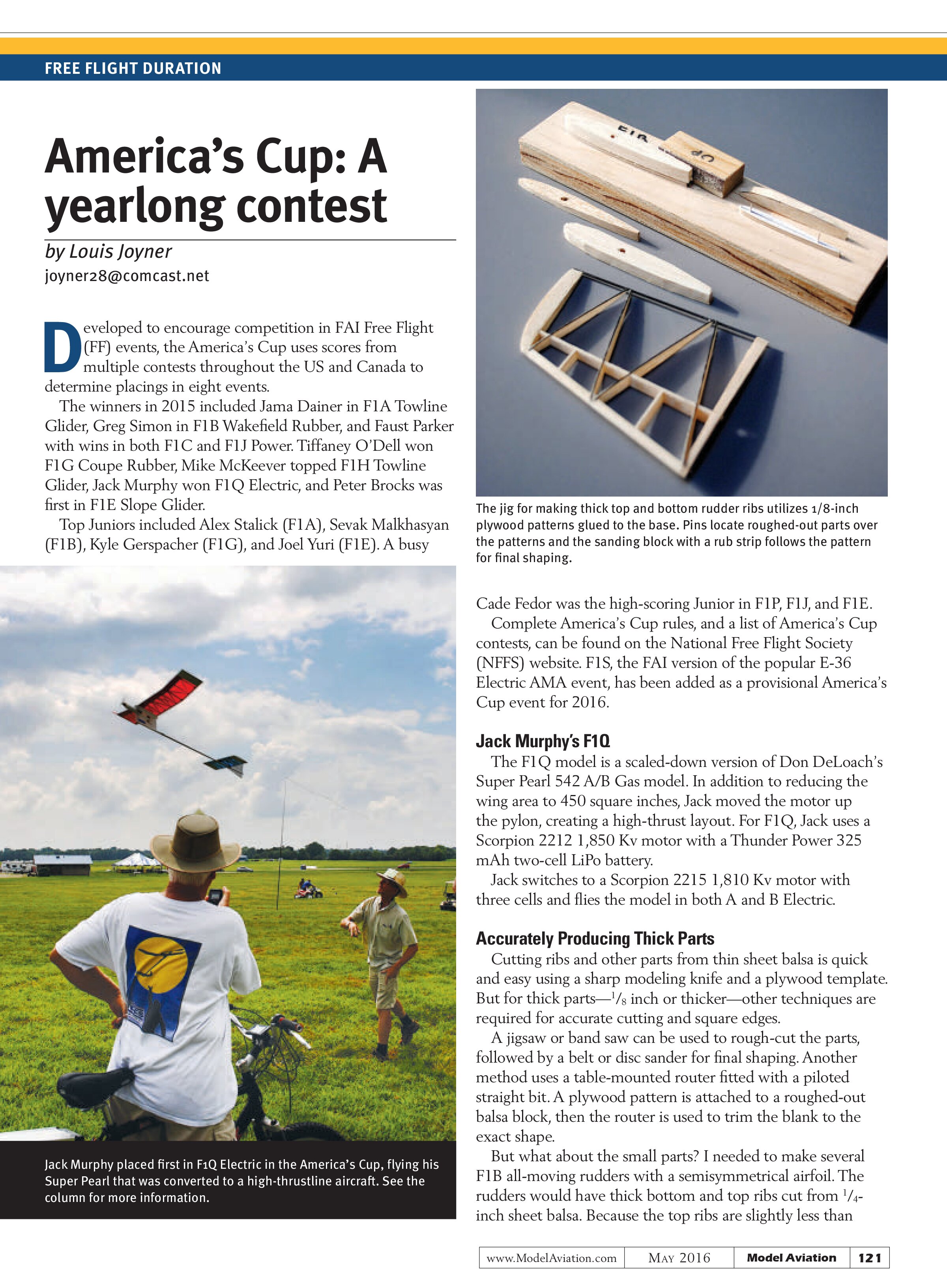
I adapted my familiar router-table method, but scaled it down to work with the smaller pieces. I first cut and sanded accurate patterns for the top and bottom ribs from ⅛-inch plywood. Both were made to full airfoil shape. (The front of each pattern was not cut away for the leading edge [LE]. You’ll see why later.)
Next, I glued the two patterns to a piece of scrap ¾-inch plywood, leaving approximately an inch of clearance around each pattern. Because the bottom rib would receive a piece of carbon-fiber tube for mounting the rudder, I drilled a hole in the bottom pattern and inserted a short piece of dowel as a locating peg. I drilled small holes approximately ½ inch from the ends of each pattern and glued in cut-down T-pins with the points up.
Blanks for both the bottom and top ribs were rough cut to shape. A hole to fit the dowel peg was drilled in each of the lower rib blanks using a drill press.
To sand the blanks to the exact shape, I used a sanding block made from a block of pine. On one long side, I glued a ⅛-inch piece of 1/₆₄ plywood flush with the bottom. This would act as a rub strip against the ⅛-inch plywood patterns—in other words, a low-tech version of the pilot bearing on a router bit.
Above the rub strip, I attached a small piece of adhesive-backed 220-grit sandpaper. The actual shaping of the parts was quick—simply push the blanks down over the patterns and sand until the rub strip hits the pattern.
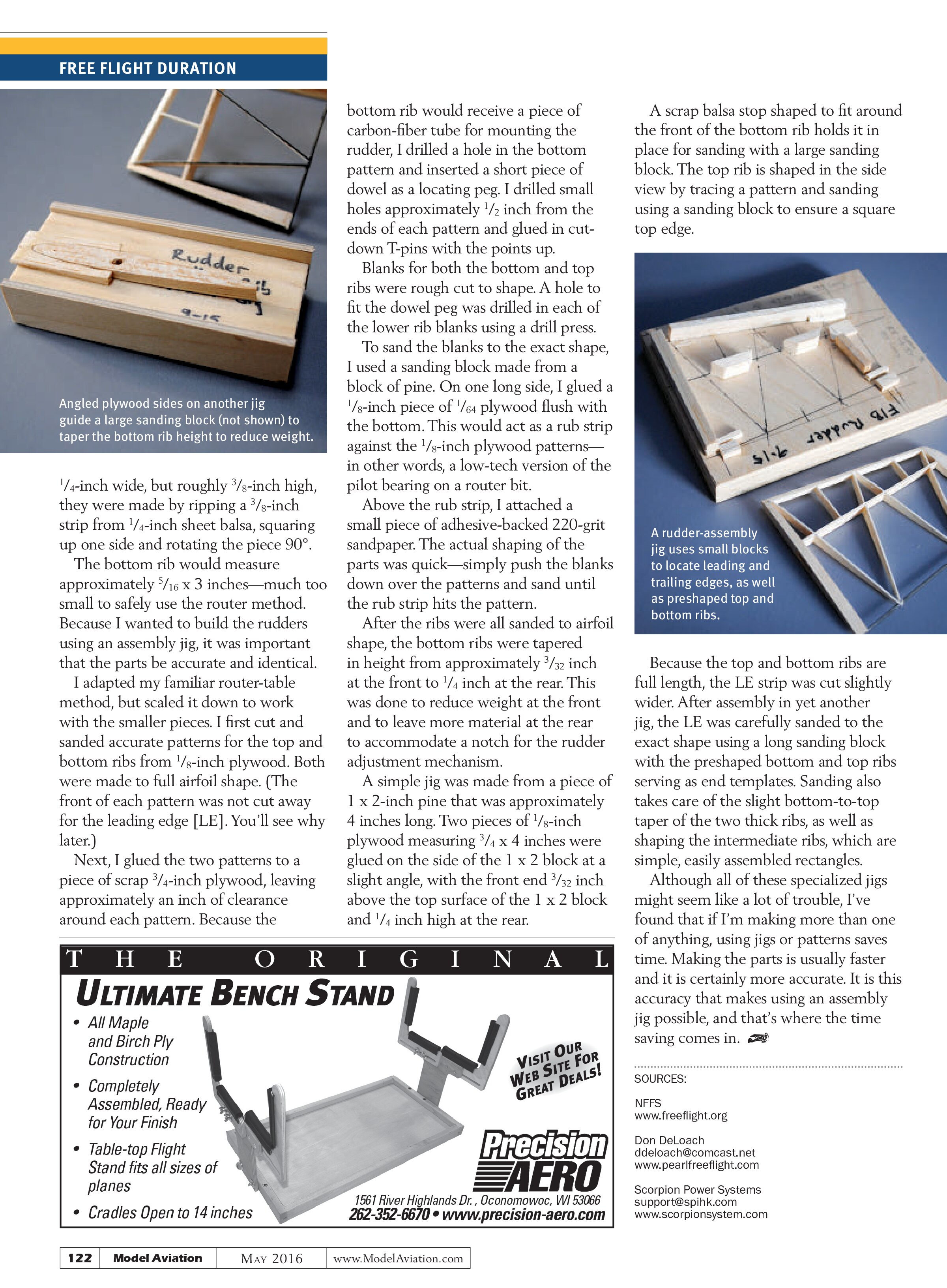
After the ribs were all sanded to airfoil shape, the bottom ribs were tapered in height from approximately ³/₃₂ inch at the front to ¼ inch at the rear. This was done to reduce weight at the front and to leave more material at the rear to accommodate a notch for the rudder adjustment mechanism.
A simple jig was made from a piece of 1 x 2-inch pine that was approximately 4 inches long. Two pieces of ⅛-inch plywood measuring ¾ x 4 inches were glued on the side of the 1 x 2 block at a slight angle, with the front end ³/₃₂ inch above the top surface of the 1 x 2 block and ¼ inch high at the rear.
A scrap balsa stop shaped to fit around the front of the bottom rib holds it in place for sanding with a large sanding block. The top rib is shaped in the side view by tracing a pattern and sanding using a sanding block to ensure a square top edge.

Because the top and bottom ribs are full length, the LE strip was cut slightly wider. After assembly in yet another jig, the LE was carefully sanded to the exact shape using a long sanding block with the preshaped bottom and top ribs serving as end templates. Sanding also takes care of the slight bottom-to-top taper of the two thick ribs, as well as shaping the intermediate ribs, which are simple, easily assembled rectangles.
Although all of these specialized jigs might seem like a lot of trouble, I’ve found that if I’m making more than one of anything, using jigs or patterns saves time. Making the parts is usually faster and it is certainly more accurate. It is this accuracy that makes using an assembly jig possible, and that’s where the time saving comes in.
SOURCES:
Don DeLoach
ddeloach@comcast.net
www.pearlfreeflight.com
Scorpion Power Systems
support@spihk.com
www.scorpionsystem.com