Sequence for attaching tail surfaces
Bob Aberle
baberle@optonline.net
Q626: I’ve noticed a trend lately, where modelers are being encouraged to get back into building model aircraft. Model Aviation has run several articles on that subject, and I understand that more are planned. Because you have published so many aircraft designs throughout the years, could you possibly share some of your skills with us?
A626: This question opens the door for me. As of this writing, I have 126 model aircraft published since 1970. Of those, 65 have been micro, indoor, and small park flyers. I’ve been able to make the construction simple so that these little airplanes can be built in only a few days and at little expense.
One interesting part of my small airplane assembly process is to use a specific sequence in mounting the stabilizer and vertical fin to the rear of the aircraft’s fuselage. There are probably several ways of doing this, but follow me as I explain my sequence. I’ve arranged the photos in order to make it easy to understand.
The airplane I’m using as an example is a revisit to a 1974 design called the Bizzy-Bee. It has approximately 100 square inches of wing area and only weighs 5.5 ounces. It recently appeared in the December 2015 issue of RC Micro World.
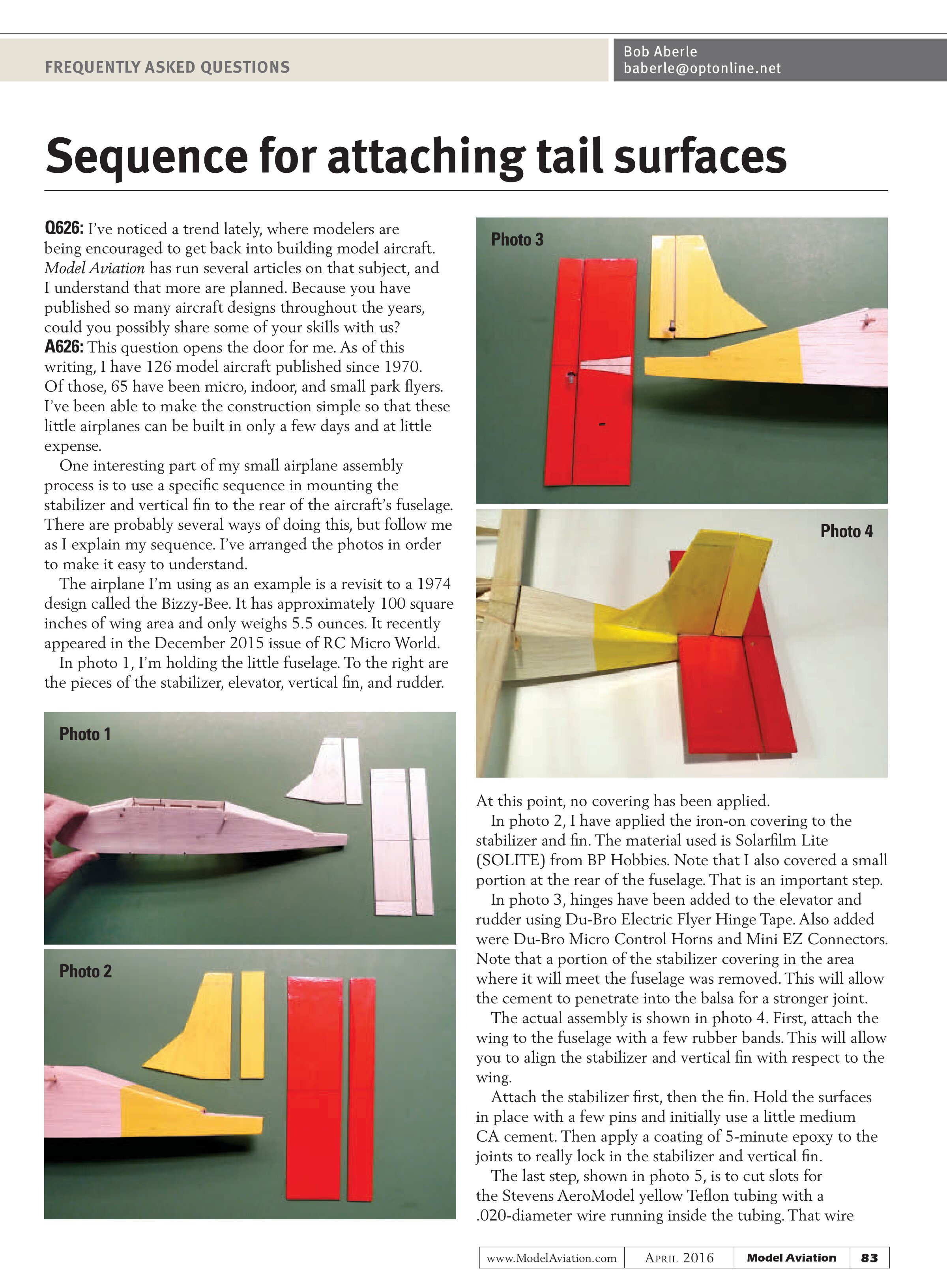
In photo 1, I’m holding the little fuselage. To the right are the pieces of the stabilizer, elevator, vertical fin, and rudder.


At this point, no covering has been applied.
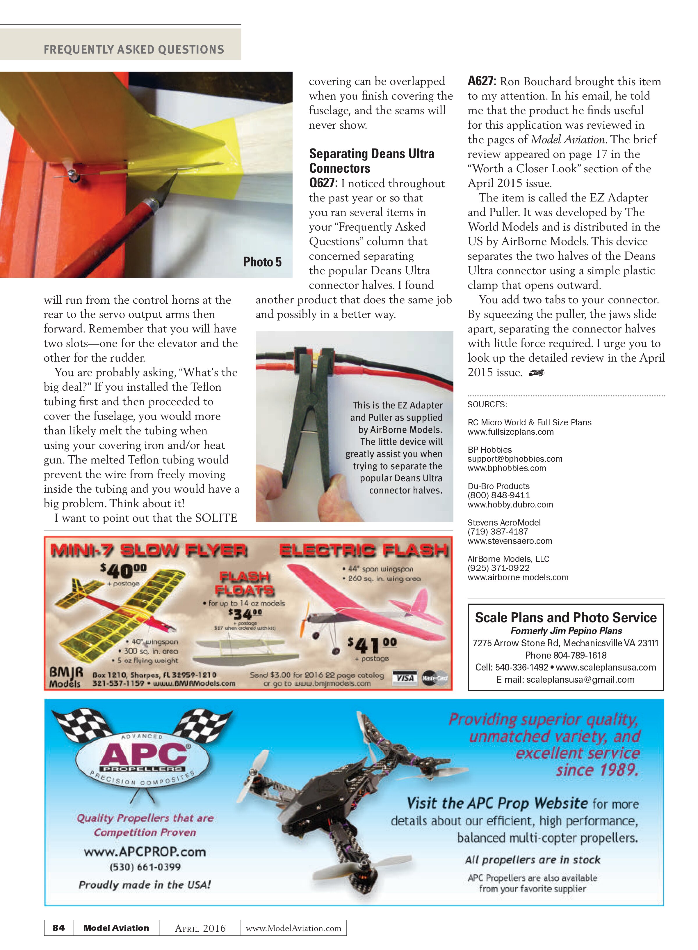
In photo 2, I have applied the iron-on covering to the stabilizer and fin. The material used is Solarfilm Lite (SOLITE) from BP Hobbies. Note that I also covered a small portion at the rear of the fuselage. That is an important step.
In photo 3, hinges have been added to the elevator and rudder using Du-Bro Electric Flyer Hinge Tape. Also added were Du-Bro Micro Control Horns and Mini EZ Connectors. Note that a portion of the stabilizer covering in the area where it will meet the fuselage was removed. This will allow the cement to penetrate into the balsa for a stronger joint.
The actual assembly is shown in photo 4. First, attach the wing to the fuselage with a few rubber bands. This will allow you to align the stabilizer and vertical fin with respect to the wing.
Attach the stabilizer first, then the fin. Hold the surfaces in place with a few pins and initially use a little medium CA cement. Then apply a coating of 5-minute epoxy to the joints to really lock in the stabilizer and vertical fin.
The last step, shown in photo 5, is to cut slots for the Stevens AeroModel yellow Teflon tubing with a .020-diameter wire running inside the tubing. That wire
will run from the control horns at the rear to the servo output arms then forward. Remember that you will have two slots—one for the elevator and the other for the rudder.
You are probably asking, “What’s the big deal?” If you installed the Teflon tubing first and then proceeded to cover the fuselage, you would more than likely melt the tubing when using your covering iron and/or heat gun. The melted Teflon tubing would prevent the wire from freely moving inside the tubing and you would have a big problem. Think about it!
I want to point out that the SOLITE covering can be overlapped when you finish covering the fuselage, and the seams will never show.
Separating Deans Ultra Connectors
0627: I noticed throughout the past year or so that you ran several items in your “Frequently Asked Questions” column that concerned separating the popular Deans Ultra connector halves. I found another product that does the same job and possibly in a better way.

A627: Ron Bouchard brought this item to my attention. In his email, he told me that the product he finds useful for this application was reviewed in the pages of Model Aviation. The brief review appeared on page 17 in the “Worth a Closer Look” section of the April 2015 issue.
The item is called the EZ Adapter and Puller. It was developed by The World Models and is distributed in the US by AirBorne Models. This device separates the two halves of the Deans Ultra connector using a simple plastic clamp that opens outward.
You add two tabs to your connector. By squeezing the puller, the jaws slide apart, separating the connector halves with little force required. I urge you to look up the detailed review in the April 2015 issue.

SOURCES:
RC Micro World & Full Size Plans
www.fullsizeplans.com
BP Hobbies
support@bphobbies.com
www.bphobbies.com
Du-Bro Products
(800) 848-9411
www.hobby.dubro.com
Stevens AeroModel
(719) 387-4187
www.stevensaero.com
AirBorne Models, LLC
(925) 371-0922
www.airborne-models.com