Wrapping It Up
by Paul Kohlmann
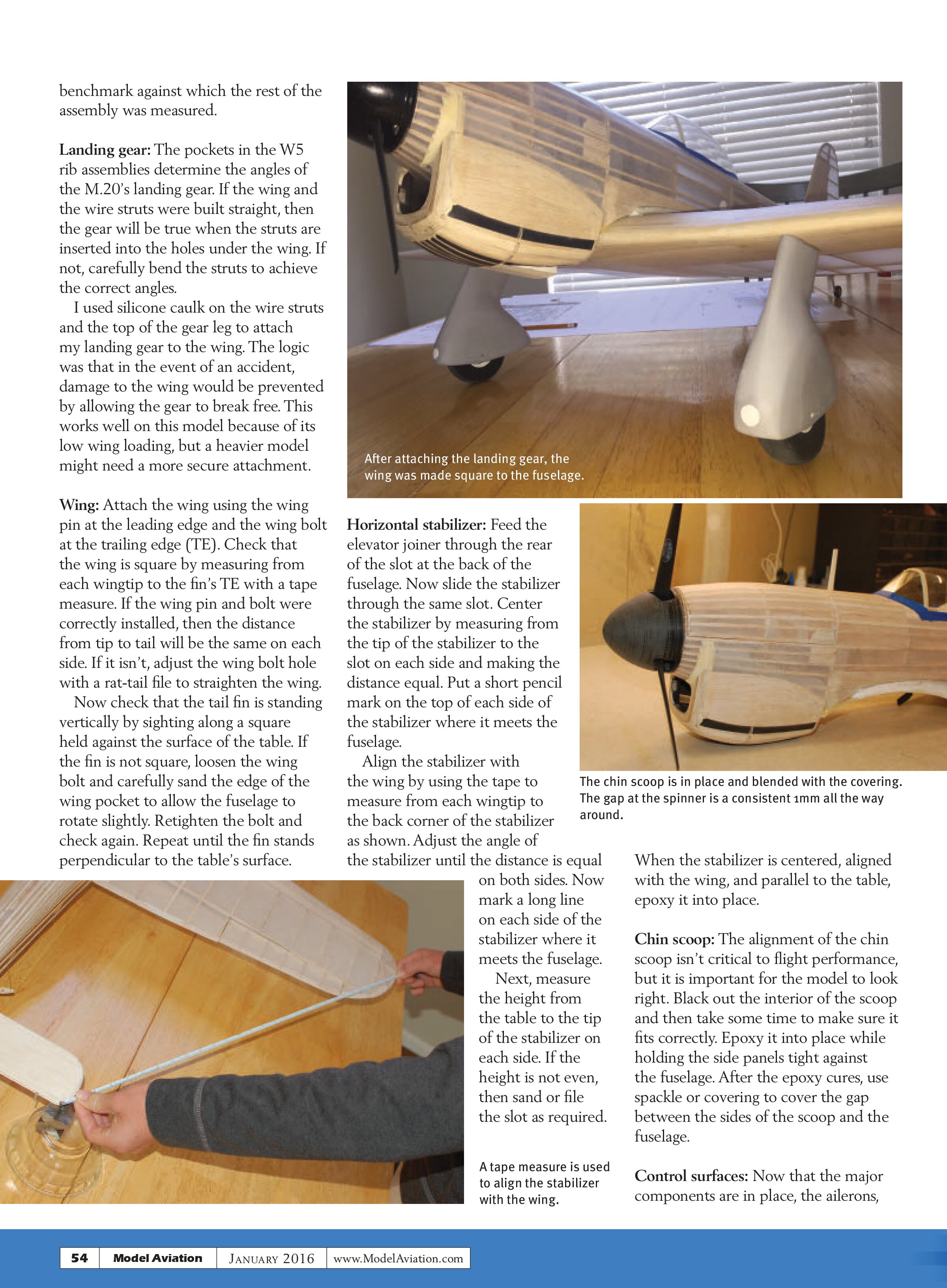
In the last 10 months, the “MA Construction Series” has covered a lot of ground! We started by gathering tools and supplies and planning our build. Then we built a balsa framework with a motor and working control surfaces. The covering and the paint went on next. In the last installment(s), we prettied up the whole thing with some custom detail parts and markings. All of this information combined was confined to 34 pages and 75 images. I use the word confined because there is so much more to say about building model aircraft, but I couldn’t get it all to fit. I feel comfortable saying that we took on the most important topics that a new builder will need to know—well, with two notable exceptions. In this final article of the series, I’ll cover assembling the Miles M.20 and then make the maiden flight.

Assembling the Airframe
We jumped over this topic between framing and covering, but it is worth a few words. After taking the time to build a wing, a fuselage, and tail parts that are straight and true, it would be a shame to put these major components together crooked.
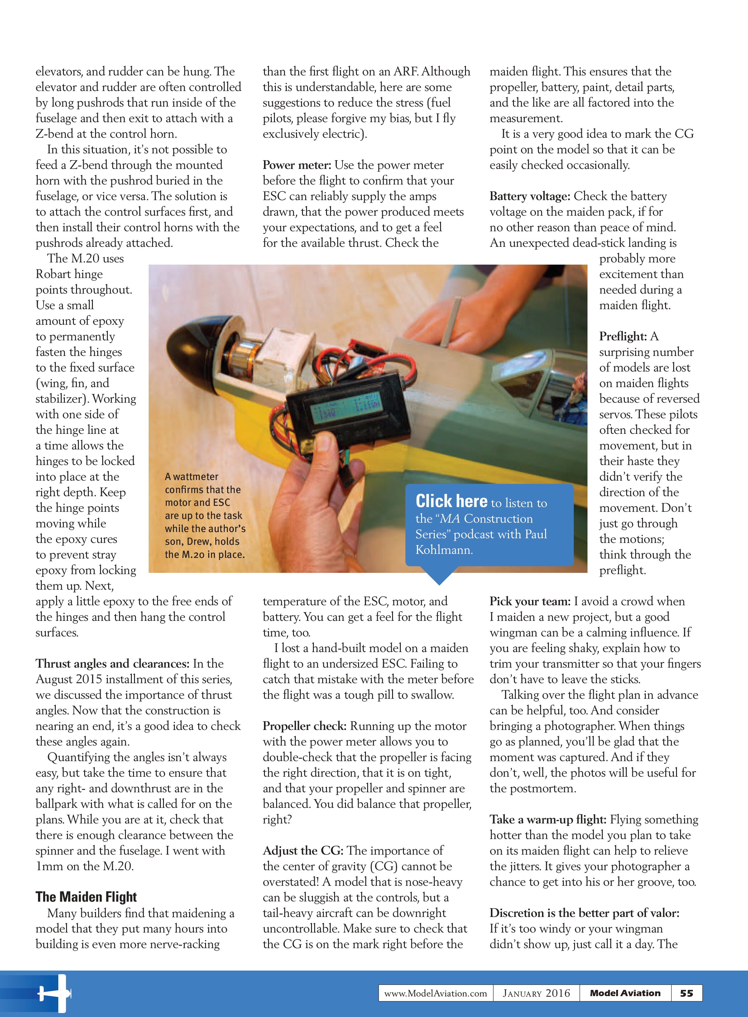
There is more than one way to assemble a model, but here are the steps that were used to assemble the M.20 prototype. The process was begun by setting the model on a flat table.
Tail fin: The M.20’s tail fin is designed to fit into a pocket in the keel of the fuselage. Because any twist in the fuselage was removed during covering, the fin was epoxied into place square with this pocket. After it cured, the fin became the

benchmark against which the rest of the assembly was measured.
Landing gear: The pockets in the W5 rib assemblies determine the angles of the M.20’s landing gear. If the wing and the wire struts were built straight, then the gear will be true when the struts are inserted into the holes under the wing. If not, carefully bend the struts to achieve the correct angles.
I used silicone caulk on the wire struts and the top of the gear leg to attach my landing gear to the wing. The logic was that in the event of an accident, damage to the wing would be prevented by allowing the gear to break free. This works well on this model because of its low wing loading, but a heavier model might need a more secure attachment.

Wing: Attach the wing using the wing pin at the leading edge and the wing bolt at the trailing edge (TE). Check that the wing is square by measuring from each wingtip to the fin’s TE with a tape measure. If the wing pin and bolt were correctly installed, then the distance from tip to tail will be the same on each side. If it isn’t, adjust the wing bolt hole with a rat-tail file to straighten the wing.
Now check that the tail fin is standing vertically by sighting along a square held against the surface of the table. If the fin is not square, loosen the wing bolt and carefully sand the edge of the wing pocket to allow the fuselage to rotate slightly. Retighten the bolt and check again. Repeat until the fin stands perpendicular to the table’s surface.

Horizontal stabilizer: Feed the elevator joiner through the rear of the slot at the back of the fuselage. Now slide the stabilizer through the same slot. Center the stabilizer by measuring from the tip of the stabilizer to the slot on each side and making the distance equal. Put a short pencil mark on the top of each side of the stabilizer where it meets the fuselage.
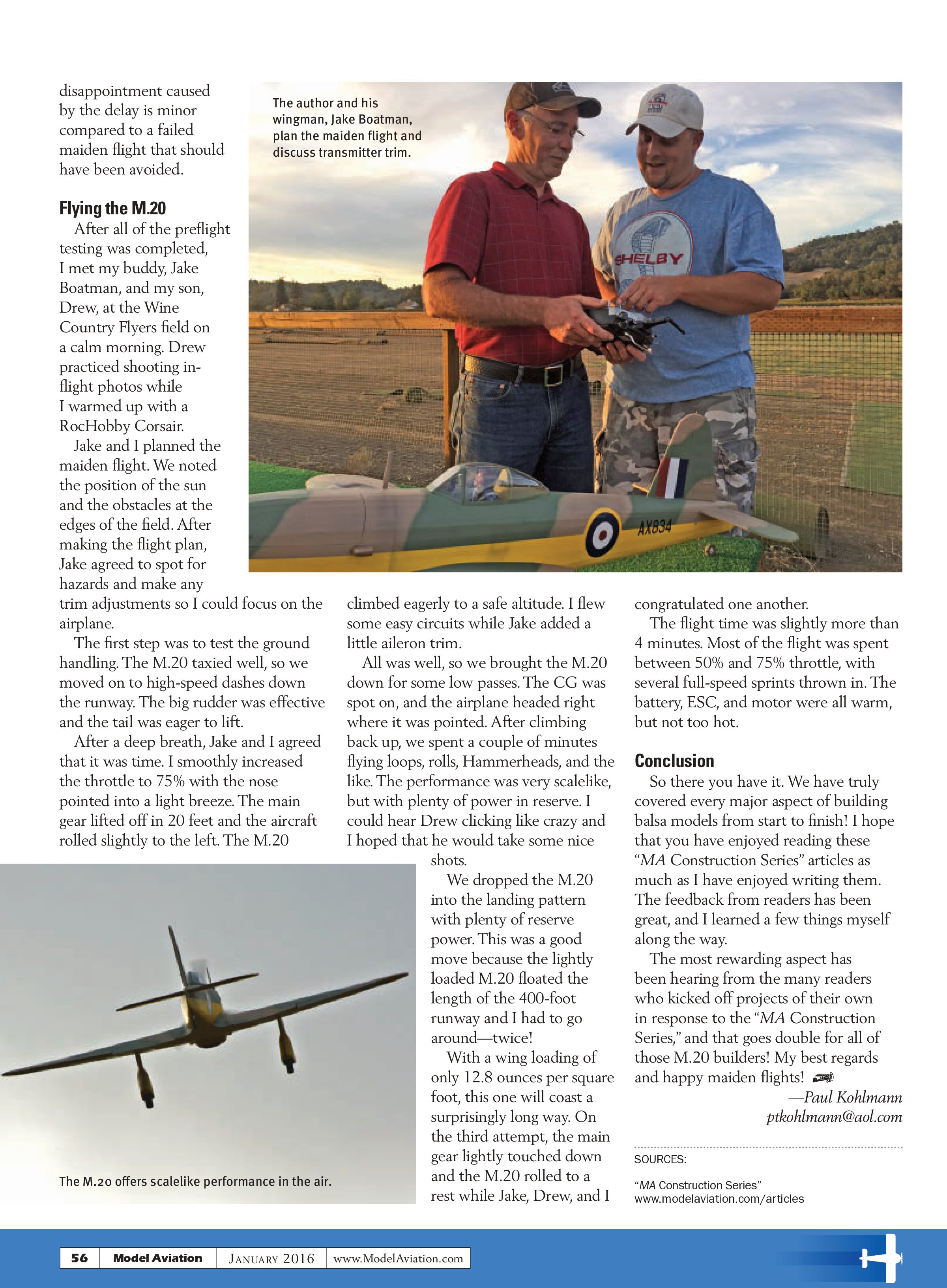
Align the stabilizer with the wing by using the tape to measure from each wingtip to the back corner of the stabilizer as shown. Adjust the angle of the stabilizer until the distance is equal on both sides. Now mark a long line on each side of the stabilizer where it meets the fuselage.
Next, measure the height from the table to the tip of the stabilizer on each side. If the height is not even, then sand or file the slot as required.

When the stabilizer is centered, aligned with the wing, and parallel to the table, epoxy it into place.
Chin scoop: The alignment of the chin scoop isn’t critical to flight performance, but it is important for the model to look right. Black out the interior of the scoop and then take some time to make sure it fits correctly. Epoxy it into place while holding the side panels tight against the fuselage. After the epoxy cures, use spackle or covering to cover the gap between the sides of the scoop and the fuselage.
Control surfaces: Now that the major components are in place, the ailerons, elevators, and rudder can be hung. The elevator and rudder are often controlled by long pushrods that run inside of the fuselage and then exit to attach with a Z-bend at the control horn.
In this situation, it’s not possible to feed a Z-bend through the mounted horn with the pushrod buried in the fuselage, or vice versa. The solution is to attach the control surfaces first, and then install their control horns with the pushrods already attached.
The M.20 uses Robart hinge points throughout. Use a small amount of epoxy to permanently fasten the hinges to the fixed surface (wing, fin, and stabilizer). Working with one side of the hinge line at a time allows the hinges to be locked into place at the right depth. Keep the hinge points moving while the epoxy cures to prevent stray epoxy from locking them up. Next, apply a little epoxy to the free ends of the hinges and then hang the control surfaces.
Thrust angles and clearances: In the August 2015 installment of this series, we discussed the importance of thrust angles. Now that the construction is nearing an end, it’s a good idea to check these angles again.
Quantifying the angles isn’t always easy, but take the time to ensure that any right- and downthrust are in the ballpark with what is called for on the plans. While you are at it, check that there is enough clearance between the spinner and the fuselage. I went with 1mm on the M.20.
The Maiden Flight
Many builders find that maidening a model that they put many hours into building is even more nerve-racking than the first flight on an ARF. Although this is understandable, here are some suggestions to reduce the stress (fuel pilots, please forgive my bias, but I fly exclusively electric).
Power meter: Use the power meter before the flight to confirm that your ESC can reliably supply the amps drawn, that the power produced meets your expectations, and to get a feel for the available thrust. Check the temperature of the ESC, motor, and battery. You can get a feel for the flight time, too.
I lost a hand-built model on a maiden flight to an undersized ESC. Failing to catch that mistake with the meter before the flight was a tough pill to swallow.
Propeller check: Running up the motor with the power meter allows you to double-check that the propeller is facing the right direction, that it is on tight, and that your propeller and spinner are balanced. You did balance that propeller, right?
Adjust the CG: The importance of the center of gravity (CG) cannot be overstated! A model that is nose-heavy can be sluggish at the controls, but a tail-heavy aircraft can be downright uncontrollable. Make sure to check that the CG is on the mark right before the maiden flight. This ensures that the propeller, battery, paint, detail parts, and the like are all factored into the measurement.
It is a very good idea to mark the CG point on the model so that it can be easily checked occasionally.
Battery voltage: Check the battery voltage on the maiden pack, if for no other reason than peace of mind. An unexpected dead-stick landing is probably more excitement than needed during a maiden flight.
Preflight: A surprising number of models are lost on maiden flights because of reversed servos. These pilots often checked for movement, but in their haste they didn’t verify the direction of the movement. Don’t just go through the motions; think through the preflight.
Pick your team: I avoid a crowd when I maiden a new project, but a good wingman can be a calming influence. If you are feeling shaky, explain how to trim your transmitter so that your fingers don’t have to leave the sticks.
Talking over the flight plan in advance can be helpful, too. And consider bringing a photographer. When things go as planned, you’ll be glad that the moment was captured. And if they don’t, well, the photos will be useful for the postmortem.
Take a warm-up flight: Flying something hotter than the model you plan to take on its maiden flight can help to relieve the jitters. It gives your photographer a chance to get into his or her groove, too.
Discretion is the better part of valor: If it’s too windy or your wingman didn’t show up, just call it a day. The

disappointment caused by the delay is minor compared to a failed maiden flight that should have been avoided.

Flying the M.20
After all of the preflight testing was completed, I met my buddy, Jake Boatman, and my son, Drew, at the Wine Country Flyers field on a calm morning. Drew practiced shooting in-flight photos while I warmed up with a RocHobby Corsair.
Jake and I planned the maiden flight. We noted the position of the sun and the obstacles at the edges of the field. After making the flight plan, Jake agreed to spot for hazards and make any trim adjustments so I could focus on the airplane.
The first step was to test the ground handling. The M.20 taxied well, so we moved on to high-speed dashes down the runway. The big rudder was effective and the tail was eager to lift.
After a deep breath, Jake and I agreed that it was time. I smoothly increased the throttle to 75% with the nose pointed into a light breeze. The main gear lifted off in 20 feet and the aircraft rolled slightly to the left. The M.20

climbed eagerly to a safe altitude. I flew some easy circuits while Jake added a little aileron trim.
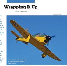
All was well, so we brought the M.20 down for some low passes. The CG was spot on, and the airplane headed right where it was pointed. After climbing back up, we spent a couple of minutes flying loops, rolls, Hammerheads, and the like. The performance was very scalelike, but with plenty of power in reserve. I could hear Drew clicking like crazy and I hoped that he would take some nice shots.
We dropped the M.20 into the landing pattern with plenty of reserve power. This was a good move because the lightly loaded M.20 floated the length of the 400-foot runway and I had to go around—twice!
With a wing loading of only 12.8 ounces per square foot, this one will coast a surprisingly long way. On the third attempt, the main gear lightly touched down and the M.20 rolled to a rest while Jake, Drew, and I congratulated one another.
The flight time was slightly more than 4 minutes. Most of the flight was spent between 50% and 75% throttle, with several full-speed sprints thrown in. The battery, ESC, and motor were all warm, but not too hot.
Conclusion
So there you have it. We have truly covered every major aspect of building balsa models from start to finish! I hope that you have enjoyed reading these “MA Construction Series” articles as much as I have enjoyed writing them. The feedback from readers has been great, and I learned a few things myself along the way.
The most rewarding aspect has been hearing from the many readers who kicked off projects of their own in response to the “MA Construction Series,” and that goes double for all of those M.20 builders! My best regards and happy maiden flights!
—Paul Kohlmann
ptkohlmann@aol.com
SOURCES:
“MA Construction Series”
www.modelaviation.com/articles