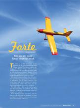
Forte
by Dave Horvath
Build your own Classic Pattern competition aircraft

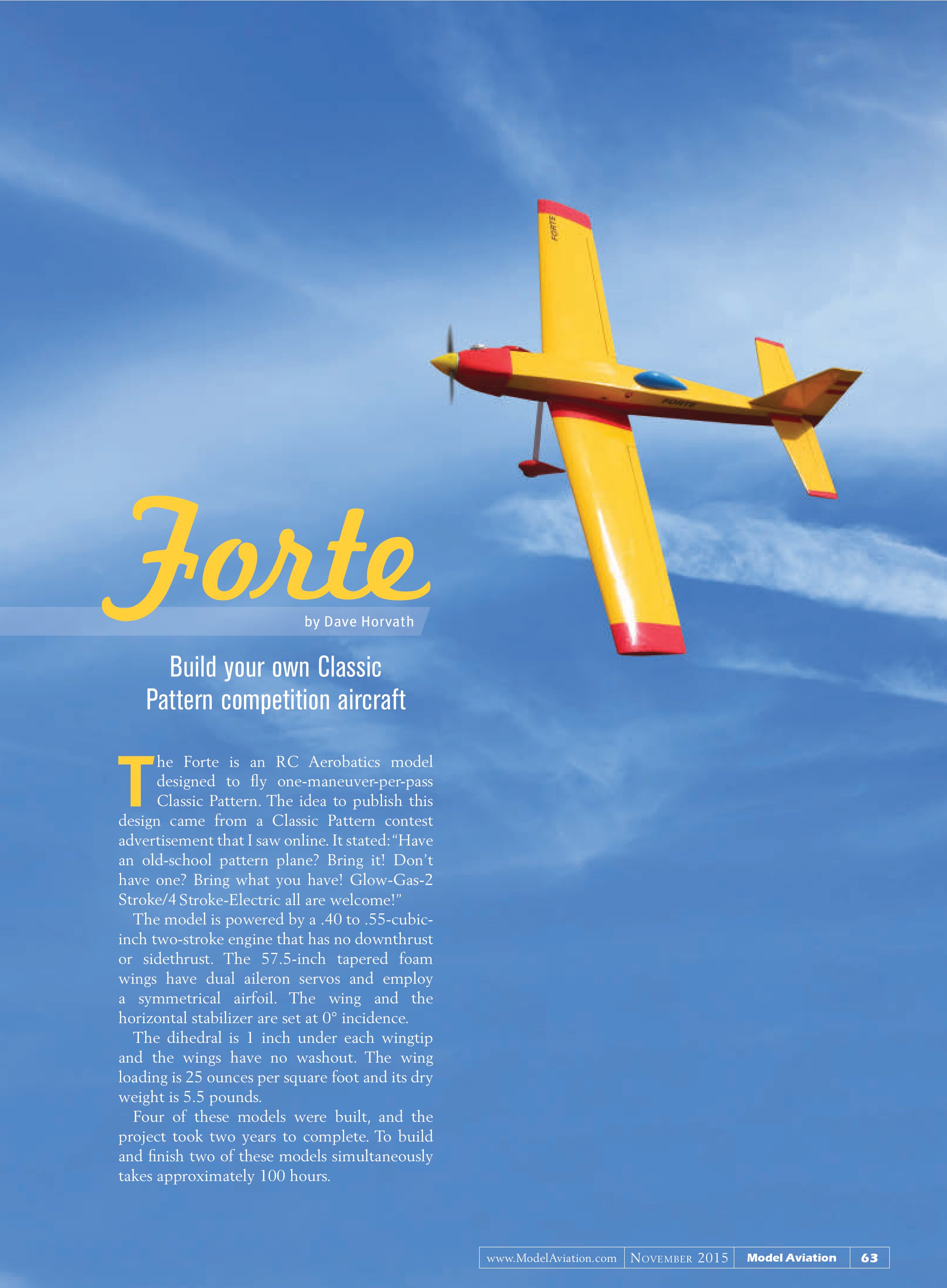
The Forte is an RC Aerobatics model designed to fly one-maneuver-per-pass Classic Pattern. The idea to publish this design came from a Classic Pattern contest advertisement that I saw online. It stated: “Have an old-school pattern plane? Bring it! Don’t have one? Bring what you have! Glow-Gas-2 Stroke/4 Stroke-Electric all are welcome!”
The model is powered by a .40 to .55-cubic-inch two-stroke engine that has no downthrust or sidethrust. The 57.5-inch tapered foam wings have dual aileron servos and employ a symmetrical airfoil. The wing and the horizontal stabilizer are set at 0° incidence.
The dihedral is 1 inch under each wingtip and the wings have no washout. The wing loading is 25 ounces per square foot and its dry weight is 5.5 pounds.
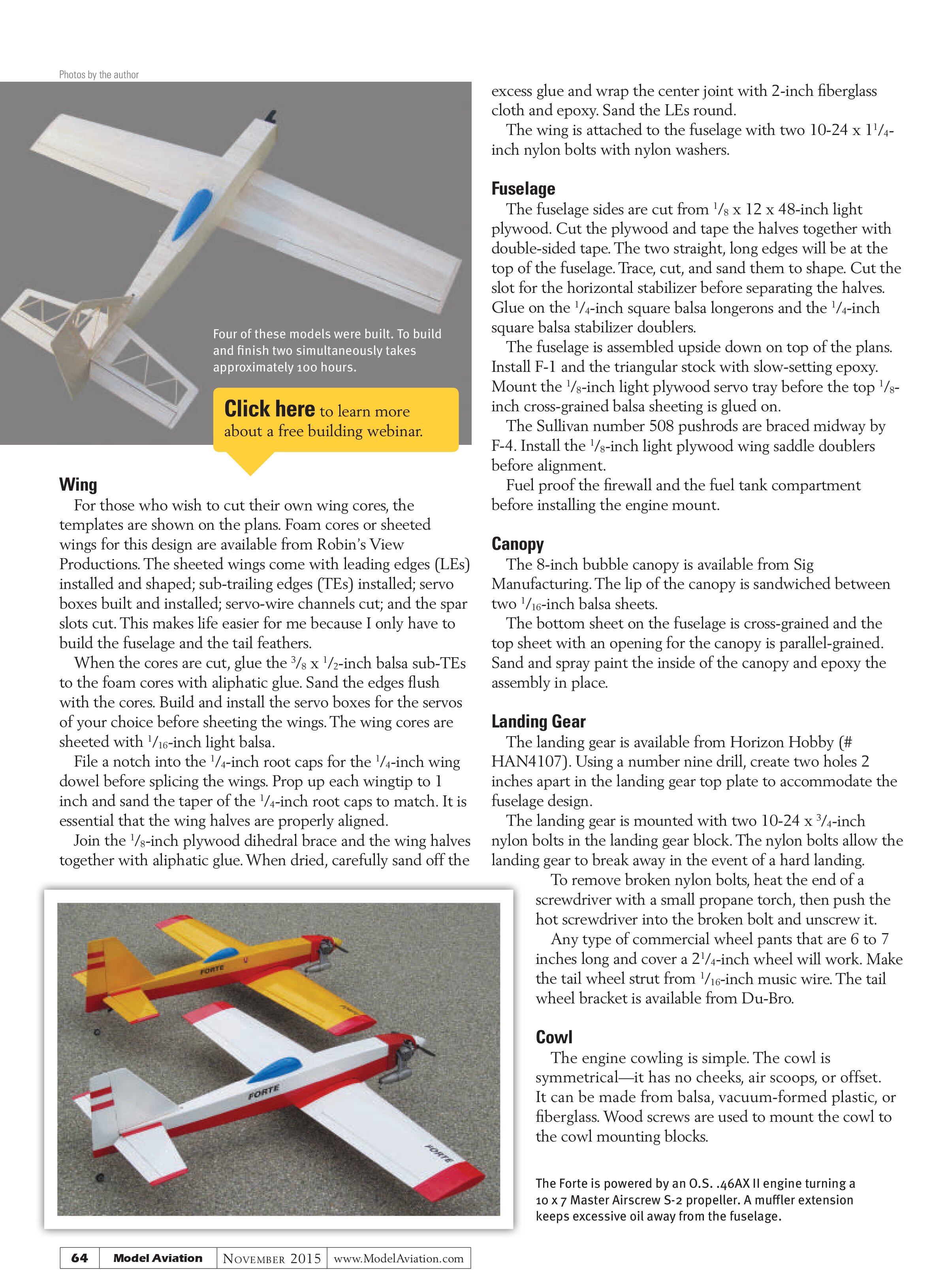
Four of these models were built, and the project took two years to complete. To build and finish two of these models simultaneously takes approximately 100 hours.

Wing
For those who wish to cut their own wing cores, the templates are shown on the plans. Foam cores or sheeted wings for this design are available from Robin’s View Productions. The sheeted wings come with leading edges (LEs) installed and shaped; sub-trailing edges (TEs) installed; servo boxes built and installed; servo-wire channels cut; and the spar slots cut. This makes life easier for me because I only have to build the fuselage and the tail feathers.
When the cores are cut, glue the ⅜ x ½-inch balsa sub-TEs to the foam cores with aliphatic glue. Sand the edges flush with the cores. Build and install the servo boxes for the servos of your choice before sheeting the wings. The wing cores are sheeted with ¹⁄₁₆-inch light balsa.
File a notch into the ¼-inch root caps for the ¼-inch wing dowel before splicing the wings. Prop up each wingtip to 1 inch and sand the taper of the ¼-inch root caps to match. It is essential that the wing halves are properly aligned.
Join the ⅛-inch plywood dihedral brace and the wing halves together with aliphatic glue. When dried, carefully sand off the excess glue and wrap the center joint with 2-inch fiberglass cloth and epoxy. Sand the LEs round.
The wing is attached to the fuselage with two 10-24 x 1¼-inch nylon bolts with nylon washers.

Fuselage
The fuselage sides are cut from ⅛ x 12 x 48-inch light plywood. Cut the plywood and tape the halves together with double-sided tape. The two straight, long edges will be at the top of the fuselage. Trace, cut, and sand them to shape. Cut the slot for the horizontal stabilizer before separating the halves. Glue on the ¼-inch square balsa longerons and the ¼-inch square balsa stabilizer doublers.
The fuselage is assembled upside down on top of the plans. Install F-1 and the triangular stock with slow-setting epoxy. Mount the ⅛-inch light plywood servo tray before the top ⅛-inch cross-grained balsa sheeting is glued on.
The Sullivan number 508 pushrods are braced midway by F-4. Install the ⅛-inch light plywood wing saddle doublers before alignment.
Fuel proof the firewall and the fuel tank compartment before installing the engine mount.
Canopy
The 8-inch bubble canopy is available from Sig Manufacturing. The lip of the canopy is sandwiched between two ¹⁄₁₆-inch balsa sheets.
The bottom sheet on the fuselage is cross-grained and the top sheet with an opening for the canopy is parallel-grained. Sand and spray paint the inside of the canopy and epoxy the assembly in place.
Landing Gear
The landing gear is available from Horizon Hobby (# HAN4107). Using a number nine drill, create two holes 2 inches apart in the landing gear top plate to accommodate the fuselage design.
The landing gear is mounted with two 10-24 x ¾-inch nylon bolts in the landing gear block. The nylon bolts allow the landing gear to break away in the event of a hard landing.
To remove broken nylon bolts, heat the end of a screwdriver with a small propane torch, then push the hot screwdriver into the broken bolt and unscrew it.
Any type of commercial wheel pants that are 6 to 7 inches long and cover a 2¼-inch wheel will work. Make the tail wheel strut from ¹⁄₁₆-inch music wire. The tail wheel bracket is available from Du-Bro.
Cowl
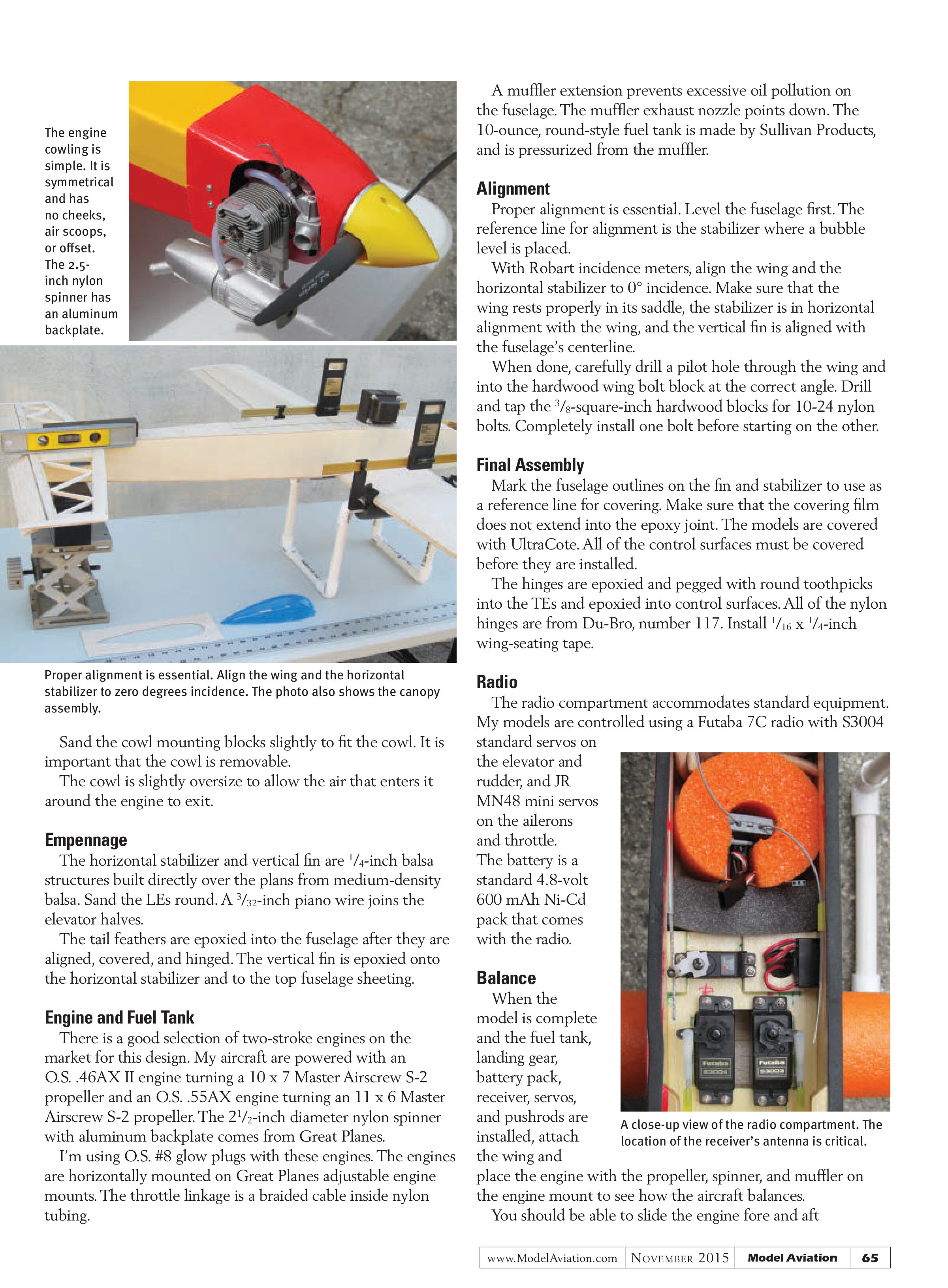
The engine cowling is simple. The cowl is symmetrical—it has no cheeks, air scoops, or offset. It can be made from balsa, vacuum-formed plastic, or fiberglass. Wood screws are used to mount the cowl to the cowl mounting blocks.
The Forte is powered by an O.S. .46AX II engine turning a 10 x 7 Master Airscrew S-2 propeller. A muffler extension keeps excessive oil away from the fuselage.

Sand the cowl mounting blocks slightly to fit the cowl. It is important that the cowl is removable.
The cowl is slightly oversize to allow the air that enters it around the engine to exit.
Empennage
The horizontal stabilizer and vertical fin are ¼-inch balsa structures built directly over the plans from medium-density balsa. Sand the LEs round. A ³⁄₃₂-inch piano wire joins the elevator halves.
The tail feathers are epoxied into the fuselage after they are aligned, covered, and hinged. The vertical fin is epoxied onto the horizontal stabilizer and to the top fuselage sheeting.
Engine and Fuel Tank
There is a good selection of two-stroke engines on the market for this design. My aircraft are powered with an O.S. .46AX II engine turning a 10 x 7 Master Airscrew S-2 propeller and an O.S. .55AX engine turning an 11 x 6 Master Airscrew S-2 propeller. The 2½-inch diameter nylon spinner with aluminum backplate comes from Great Planes.
I’m using O.S. #8 glow plugs with these engines. The engines are horizontally mounted on Great Planes adjustable engine mounts. The throttle linkage is a braided cable inside nylon tubing.
A muffler extension prevents excessive oil pollution on the fuselage. The muffler exhaust nozzle points down. The 10-ounce, round-style fuel tank is made by Sullivan Products, and is pressurized from the muffler.
Alignment
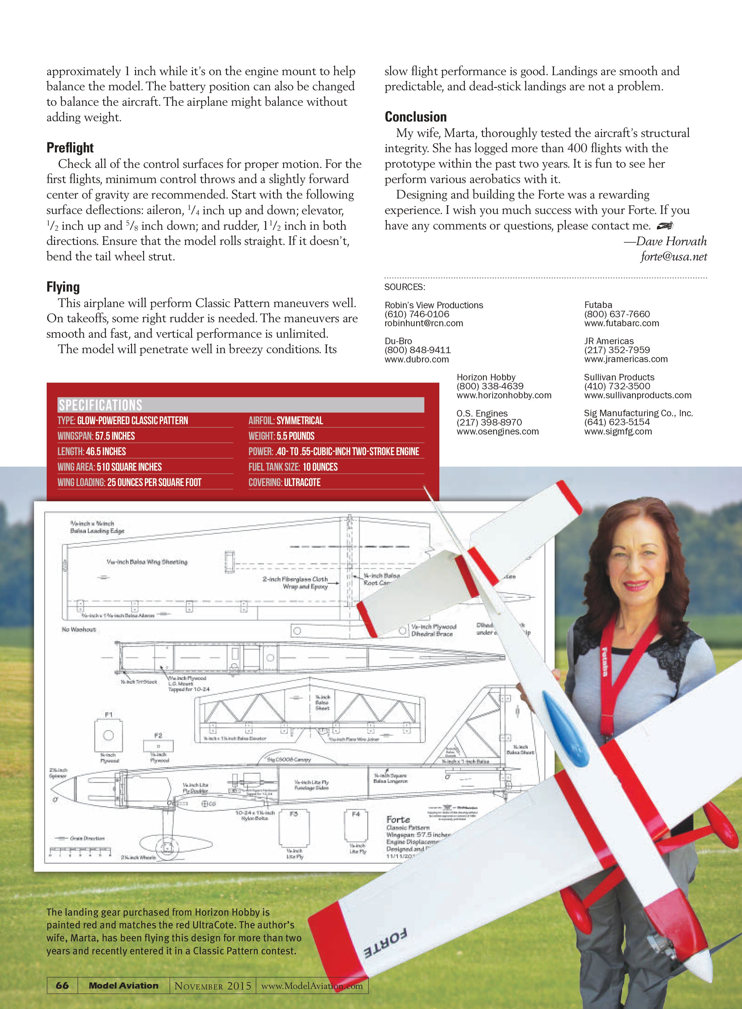
Proper alignment is essential. Level the fuselage first. The reference line for alignment is the stabilizer where a bubble level is placed.
With Robart incidence meters, align the wing and the horizontal stabilizer to 0° incidence. Make sure that the wing rests properly in its saddle, the stabilizer is in horizontal alignment with the wing, and the vertical fin is aligned with the fuselage’s centerline.
When done, carefully drill a pilot hole through the wing and into the hardwood wing bolt block at the correct angle. Drill and tap the ⅜-square-inch hardwood blocks for 10-24 nylon bolts. Completely install one bolt before starting on the other.

Final Assembly
Mark the fuselage outlines on the fin and stabilizer to use as a reference line for covering. Make sure that the covering film does not extend into the epoxy joint. The models are covered with UltraCote. All of the control surfaces must be covered before they are installed.
The hinges are epoxied and pegged with round toothpicks into the TEs and epoxied into control surfaces. All of the nylon hinges are from Du-Bro, number 117. Install ¹⁄₁₆ x ¼-inch wing-seating tape.
Radio
The radio compartment accommodates standard equipment. My models are controlled using a Futaba 7C radio with S3004 standard servos on the elevator and rudder, and JR MN48 mini servos on the ailerons and throttle. The battery is a standard 4.8-volt 600 mAh Ni-Cd pack that comes with the radio.

Balance
When the model is complete and the fuel tank, landing gear, battery pack, receiver, servos, and pushrods are installed, attach the wing and place the engine with the propeller, spinner, and muffler on the engine mount to see how the aircraft balances.
You should be able to slide the engine fore and aft
approximately 1 inch while it’s on the engine mount to help balance the model. The battery position can also be changed to balance the aircraft. The airplane might balance without adding weight.
Preflight
Check all of the control surfaces for proper motion. For the first flights, minimum control throws and a slightly forward center of gravity are recommended. Start with the following surface deflections: aileron, ¼ inch up and down; elevator, ½ inch up and ⅝ inch down; and rudder, 1½ inch in both directions. Ensure that the model rolls straight. If it doesn’t, bend the tail wheel strut.
Flying
This airplane will perform Classic Pattern maneuvers well. On takeoffs, some right rudder is needed. The maneuvers are smooth and fast, and vertical performance is unlimited.
The model will penetrate well in breezy conditions. Its slow flight performance is good. Landings are smooth and predictable, and dead-stick landings are not a problem.
Conclusion
My wife, Marta, thoroughly tested the aircraft’s structural integrity. She has logged more than 400 flights with the prototype within the past two years. It is fun to see her perform various aerobatics with it.
Designing and building the Forte was a rewarding experience. I wish you much success with your Forte. If you have any comments or questions, please contact me.
—Dave Horvath
forte@usa.net
SPECIFICATIONS
TYPE: GLOW-POWERED CLASSIC PATTERN
WINGSPAN: 57.5 INCHES
LENGTH: 46.5 INCHES
WING AREA: 510 SQUARE INCHES
WING LOADING: 25 OUNCES PER SQUARE FOOT
AIRFOIL: SYMMETRICAL
WEIGHT: 5.5 POUNDS
POWER: .40- TO .55-CUBIC-INCH TWO-STROKE ENGINE
FUEL TANK SIZE: 10 OUNCES
COVERING: ULTRACOTE
SOURCES:
Robin’s View Productions
(610) 746-0106
robinhunt@rcn.com
Du-Bro
(800) 848-9411
www.dubro.com
Horizon Hobby
(800) 338-4639
www.horizonhobby.com
O.S. Engines
(217) 398-8970
www.osengines.com
Futaba
(800) 637-7660
www.futabaRC.com
JR Americas
(217) 352-7959
www.jramericas.com
Sullivan Products
(410) 732-3500
www.sullivanproducts.com
Sig Manufacturing Co., Inc.
(641) 623-5154
www.sig mfg.com