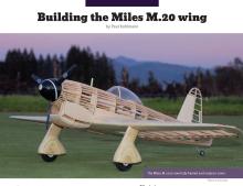
Building the Miles M.20 wing
by Paul Kohlmann

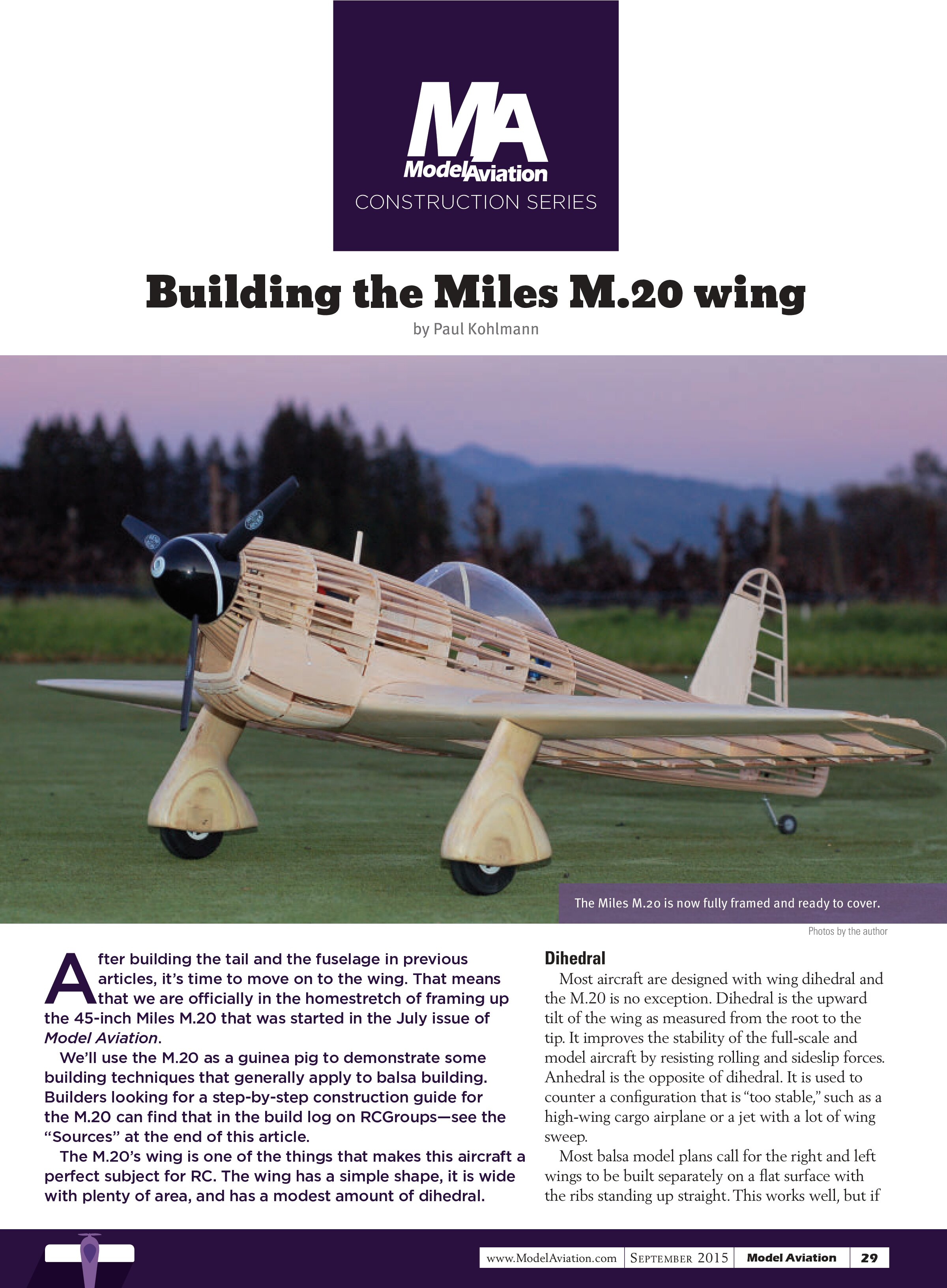
After building the tail and the fuselage in previous articles, it’s time to move on to the wing. That means that we are officially in the homestretch of framing up the 45-inch Miles M.20 that was started in the July issue of Model Aviation.
We’ll use the M.20 as a guinea pig to demonstrate some building techniques that generally apply to balsa building. Builders looking for a step-by-step construction guide for the M.20 can find that in the build log on RCGroups—see the “Sources” at the end of this article.
The M.20’s wing is one of the things that makes this aircraft a perfect subject for RC. The wing has a simple shape, it is wide with plenty of area, and has a modest amount of dihedral.
Dihedral
Most aircraft are designed with wing dihedral and the M.20 is no exception. Dihedral is the upward tilt of the wing as measured from the root to the tip. It improves the stability of the full-scale and model aircraft by resisting rolling and sideslip forces. Anhedral is the opposite of dihedral. It is used to counter a configuration that is “too stable,” such as a high-wing cargo airplane or a jet with a lot of wing sweep.
Most balsa model plans call for the right and left wings to be built separately on a flat surface with the ribs standing up straight. This works well, but if
the wing is to have dihedral, the center ribs, where the panels meet, need to be tilted.
The simplest solution is to use a dihedral gauge. This might be printed on the plans. If so, cut it out and prop it against the center rib. After the rib is aligned to the angle of the gauge, glue the rib in place.
Plans usually provide details for how to check the assembled wing’s dihedral. This normally means instructions about how to measure the space under the wingtip when the wing is on a flat surface. In addition to improving flight stability, getting the correct dihedral angle can affect how the wing fits the rest of the model.
The M.20’s wing has a dihedral break slightly inboard of the landing gear. Designers who are facing this issue will often frame each panel separately and join them later. To enable the M.20 wing to be built in just two panels, the ribs from the break to the root have tabs to lift them to the correct height from the board. This ensures that the angle of the dihedral break will be on target. A paper gauge from the plans takes care of the dihedral between the two completed wing panels by setting the angles of the center ribs.

Washout
Builders also need to know about washout. Many aircraft have an intentional twist designed into the wing. The direction of the twist is important. Washout means that the wingtip is twisted counterclockwise when the aircraft is viewed in profile and heading to the left.
The purpose of washout is to control how the aircraft stalls. Washout decreases the angle of attack of the wingtip, so that it will stall later than the root. This helps prevent the dreaded tip stall—a condition where the tip of one wing suddenly stops lifting and the aircraft unexpectedly snap rolls.

Washout is added to open structures without sheeting by lightly twisting the wing while shrinking the covering. Normally, only a couple of degrees of twisting are enough. The open structure is flexible and easily adjusted.
If the wing will be sheeted, the builder needs to exercise more care. When the wing is partially sheeted, it will become more rigid. The washout needs to be in place when the sheeting goes on.
The M.20 is sheeted from the leading edge (LE) to the main spar on top and bottom with 1/16-inch balsa. To get the washout right, pin the finished wing panel down flat to the board. Shim the wingtip with a bit of 1/8-inch balsa under the trailing edge.
Fit the upper sheeting panels then dampen their outer surfaces with water so that they curl into place. Carpenter’s glue allows their placement to be adjusted. After the upper panels fully cure, the wing is much less flexible. The bottom side can now be sheeted free from the board, setting the washout in stone.
Leading Edge
Many designs use a strip of soft balsa glued to the front of the wing panel to form the rounded LE of the airfoil. The M.20 is designed this way. Now that all of the sheeting is in place, glue a strip of 1/4-inch soft balsa to the slotted balsa LE that holds the ribs in position.
Quite a bit of the soft balsa will be removed during the shaping of the LE. An X-Acto knife or a razor plane works well to knock off the big stuff. Move on to the sanding bar with 60-grit sandpaper. It’s a good idea to protect the sheeting

with masking tape so that it doesn’t get sanded away. Sand the soft balsa until it blends smoothly with the sheeting on the top and bottom of the wing.
The soft balsa now has three surfaces: one that is tangent to the top sheeting, a second that is tangent to the bottom sheeting, and the third is the flat front face of the LE. The last step is to carefully blend these three surfaces into a smooth radius. This step is important—a nice, round LE improves the stall characteristics.

Aileron Torque Tubes
Builders have options for how to control ailerons. One is to mount a separate servo and short linkage near each of the ailerons. Alternatively, a single servo hidden in the center of the wing can control both of the ailerons.
When a single servo is used, the linkage can be a set of rods that slides into a sheath. Commonly called Sullivan rods, these linkages usually emerge from the wing near the aileron control horns.
A third option is to build a pair of simple bellcranks, known as torque rods. I’m a fan of torque rods because they are low friction, easy to adjust, and hidden inside the wing and the fuselage.
The torque rods in the M.20 prototype were made from 1/16-inch steel music wire rod and 1/8-inch carbon-fiber tubing. The wire was cut and bent to form two 90° angles. The carbon-fiber tubing was cut to length with a razor saw.
Begin the installation by drilling holes through the ribs to cradle the carbon-fiber rod. A length of music wire makes a nice, long drill bit after clipping off its end to make it sharp. Twist it through each of the ribs between the servo and the aileron then open the holes with a small rat-tail file until the carbon-fiber tube slips into place.
Next, roughen the ends of the wire cranks and then epoxy them into the carbon-fiber tube. Roughening the wire is critical to the strength of the epoxy bond. Each end of the carbon-fiber tube gets one crank. The one at the aileron points horizontally toward the tail, while the one at the servo stands up vertically.
An arm made from aluminum tubing connects the torque rod to the servo. Flatten one end of the tube with a pair of pliers then drill a hole for the Z-bend of a control rod to slip through. Epoxy this arm onto the vertical end of the torque

rod (roughen that wire!). Attach the control rod at the other end with a Du-Bro EZ Connector. For the aileron end, drill a hole through the LE of the aileron for the horizontal crank to fit into. A little scrap wood can be used to form a receiver for the wire.
The torque rod is connected to the servo with an arm from an aluminum tube, a short control rod, and an EZ Connector.

The result is a completely hidden linkage with almost no drag.
Wing Attachment
The M.20’s wing is attached at the front with a wing pin. The wing pin is made from a ¼-inch piece of hardwood dowel that is glued into a hole drilled through the LE and into the center ribs. The pin fits into a reinforced hole in the former in the front of the wing pocket.
The back of the wing is attached with a ¼ x 20 nylon screw that runs through the wing from the bottom, up through a pad in the fuselage, and into a nylon nut. Roughen one side of the nut with 60-grit sandpaper and epoxy it to the top of the wing bolt pad.
Put a little grease on the screw and thread it into the nut while the epoxy cures. This ensures that the nut is lined up and it keeps the threads free of epoxy. Turn that screw periodically as the epoxy sets up.
The correct spot for the hole through the wing can be found by replacing the screw with a sharpened ¼-20 stud. Put the fuselage on the wing and the wing pin in its hole. Line up the back of the wing with the wing pocket. Press the back of the wing gently into the sharpened stud. Drill the through hole where the mark was left in the sheeting.

Landing Gear
The oversized spats covering the M.20’s landing gear really define this airplane. Miles only built two M.20s and they could easily be distinguished by the shape of their spats. The Royal Air Force received the huge style shown here, while the Royal Navy’s Fleet Air Arm got a trimmed-down version.
Start the construction of the spats by bending the wire strut as shown on the plans. Next, pin the center layer of balsa to the plans. Glue five shaped layers of wood to one side of the center layer. After it is cured, unpin the assembly and epoxy the wire strut into the pocket in the center layer. Next, stack up the opposite side.

Shape the finished assembly with 60-grit sandpaper. Careful sanding will transform the terraced appearance to a shapely spat that only needs a little filler. Plaster or lightweight spackle works well for this.
Sand the filled spat with 120-grit sandpaper, followed by 220-grit sandpaper. Seal with water-based polyurethane or another varnish.
Make an axle from music wire or carbon-fiber tube and run it through the holes in the spat to trap a 3-inch lightweight wheel, and the landing gear is done.
Until Next Time
Now that the airframe is complete, we can move on to covering. The next time we meet we’ll test out an updated spin on silk and dope.
—Paul Kohlmann
ptkohlmann@aol.com
SOURCES:
M.20 build log
www.rcgroups.com/forums/
showthread.php?t=2306551
Hitec RCD
(858) 748-6948
www.hitecrcd.com
Du-Bro
(800) 848-9411
www.dubro.com
Manzano Laser Works
(505) 286-2640
www.manzanolaser.com
Building the M.20 Tail Group
www.ModelAviation.com/m20tail
Building the M.20 Fuselage
www.ModelAviation.com/
m20fuselage