Building the Miles M.20 fuselage
by Paul Kohlmann

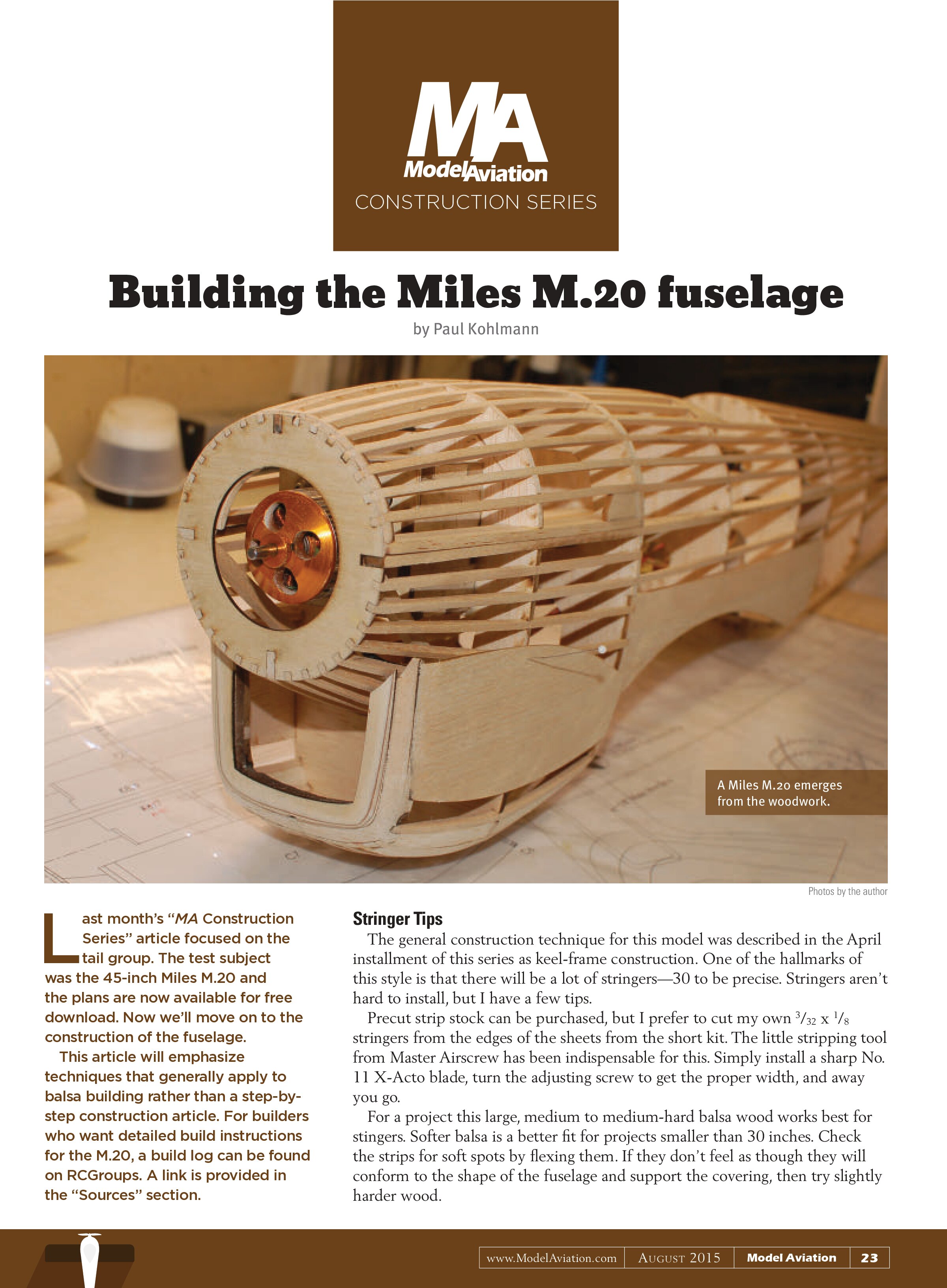
Last month’s “MA Construction Series” article focused on the tail group. The test subject was the 45-inch Miles M.20 and the plans are now available for free download. Now we’ll move on to the construction of the fuselage.
This article will emphasize techniques that generally apply to balsa building rather than a step-by-step construction article. For builders who want detailed build instructions for the M.20, a build log can be found on RCGroups. A link is provided in the “Sources” section.
Stringer Tips
The general construction technique for this model was described in the April installment of this series as keel-frame construction. One of the hallmarks of this style is that there will be a lot of stringers—30 to be precise. Stringers aren’t hard to install, but I have a few tips.
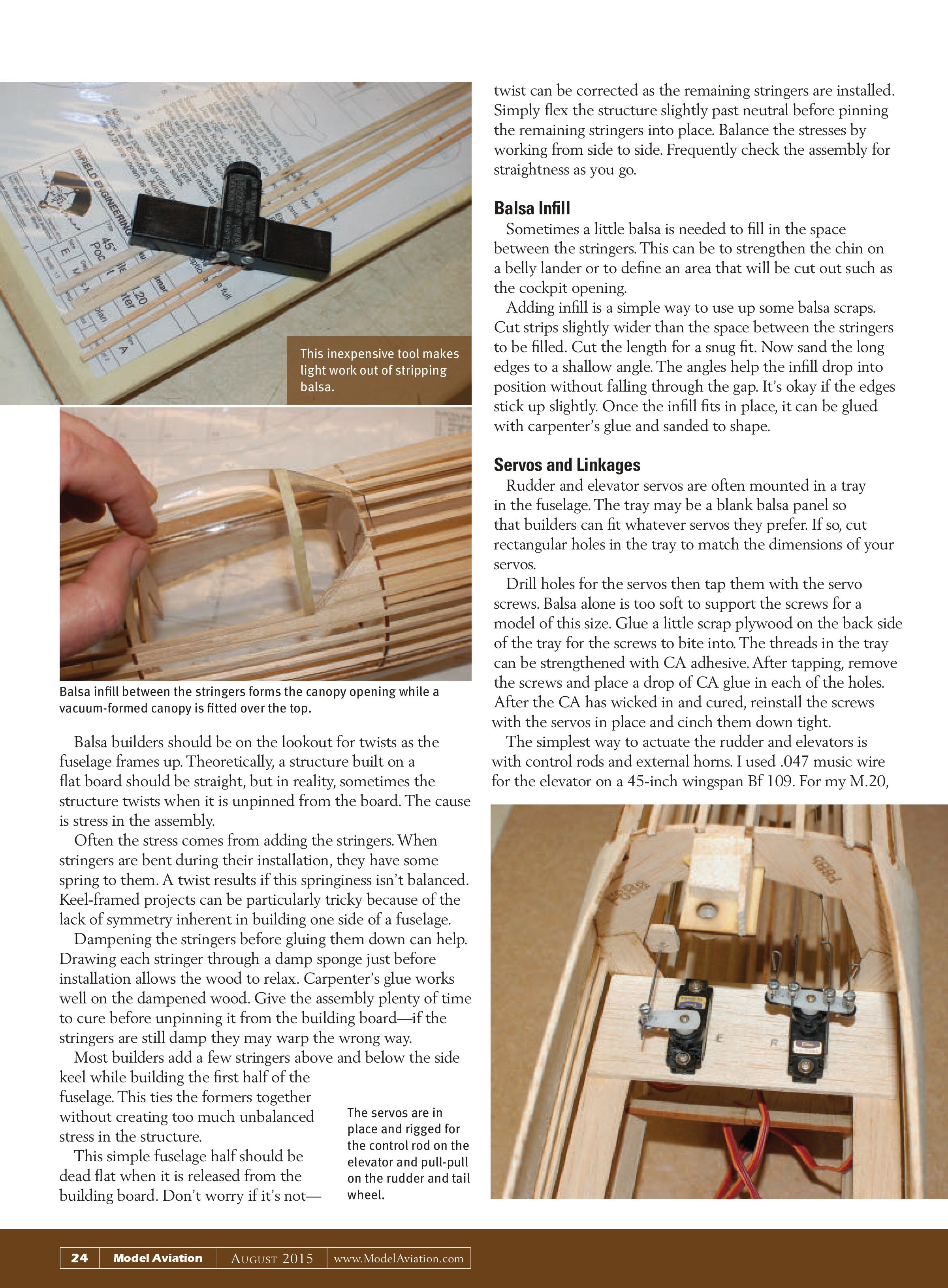
Precut strip stock can be purchased, but I prefer to cut my own ³⁄₃₂ x ¹⁄₈ stringers from the edges of the sheets from the short kit. The little stripping tool from Master Airscrew has been indispensable for this. Simply install a sharp No. 11 X-Acto blade, turn the adjusting screw to get the proper width, and away you go.
For a project this large, medium to medium-hard balsa wood works best for stringers. Softer balsa is a better fit for projects smaller than 30 inches. Check the strips for soft spots by flexing them. If they don’t feel as though they will conform to the shape of the fuselage and support the covering, then try slightly harder wood.


Balsa builders should be on the lookout for twists as the fuselage frames up. Theoretically, a structure built on a flat board should be straight, but in reality, sometimes the structure twists when it is unpinned from the board. The cause is stress in the assembly.
Often the stress comes from adding the stringers. When stringers are bent during their installation, they have some spring to them. A twist results if this springiness isn’t balanced. Keel-framed projects can be particularly tricky because of the lack of symmetry inherent in building one side of a fuselage.
Dampening the stringers before gluing them down can help. Drawing each stringer through a damp sponge just before installation allows the wood to relax. Carpenter’s glue works well on the dampened wood. Give the assembly plenty of time to cure before unpinning it from the building board—if the stringers are still damp they may warp the wrong way.
Most builders add a few stringers above and below the side keel while building the first half of the fuselage. This ties the formers together without creating too much unbalanced stress in the structure.
This simple fuselage half should be dead flat when it is released from the building board. Don’t worry if it’s not—
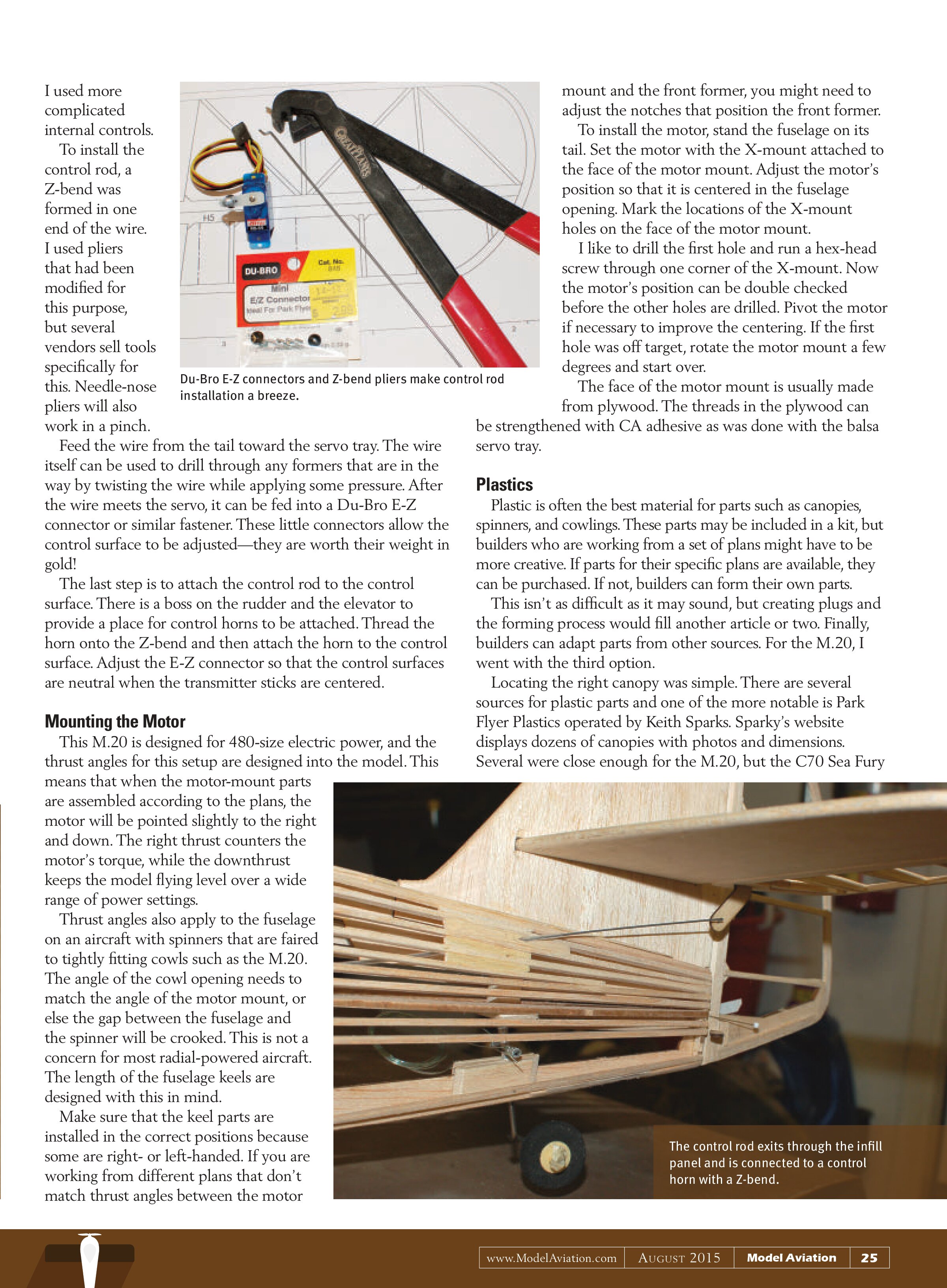
I used more complicated internal controls. To install the control rod, a Z-bend was formed in one end of the wire. I used pliers that had been modified for this purpose, but several vendors sell tools specifically for this. Needle-nose pliers will also work in a pinch.

Feed the wire from the tail toward the servo tray. The wire itself can be used to drill through any formers that are in the way by twisting the wire while applying some pressure. After the wire meets the servo, it can be fed into a Du-Bro E-Z connector or similar fastener. These little connectors allow the control surface to be adjusted—they are worth their weight in gold!
The last step is to attach the control rod to the control surface. There is a boss on the rudder and the elevator to provide a place for control horns to be attached. Thread the horn onto the Z-bend and then attach the horn to the control surface. Adjust the E-Z connector so that the control surfaces are neutral when the transmitter sticks are centered.
Mounting the Motor
This M.20 is designed for 480-size electric power, and the thrust angles for this setup are designed into the model. This means that when the motor-mount parts are assembled according to the plans, the motor will be pointed slightly to the right and down. The right thrust counters the motor’s torque, while the downthrust keeps the model flying level over a wide range of power settings.
Thrust angles also apply to the fuselage on an aircraft with spinners that are faired to tightly fitting cowls such as the M.20. The angle of the cowl opening needs to match the angle of the motor mount, or else the gap between the fuselage and the spinner will be crooked. This is not a concern for most radial-powered aircraft. The length of the fuselage keels are designed with this in mind.
Make sure that the keel parts are installed in the correct positions because some are right- or left-handed. If you are working from different plans that don’t match thrust angles between the motor mount and the front former, you might need to adjust the notches that position the front former.
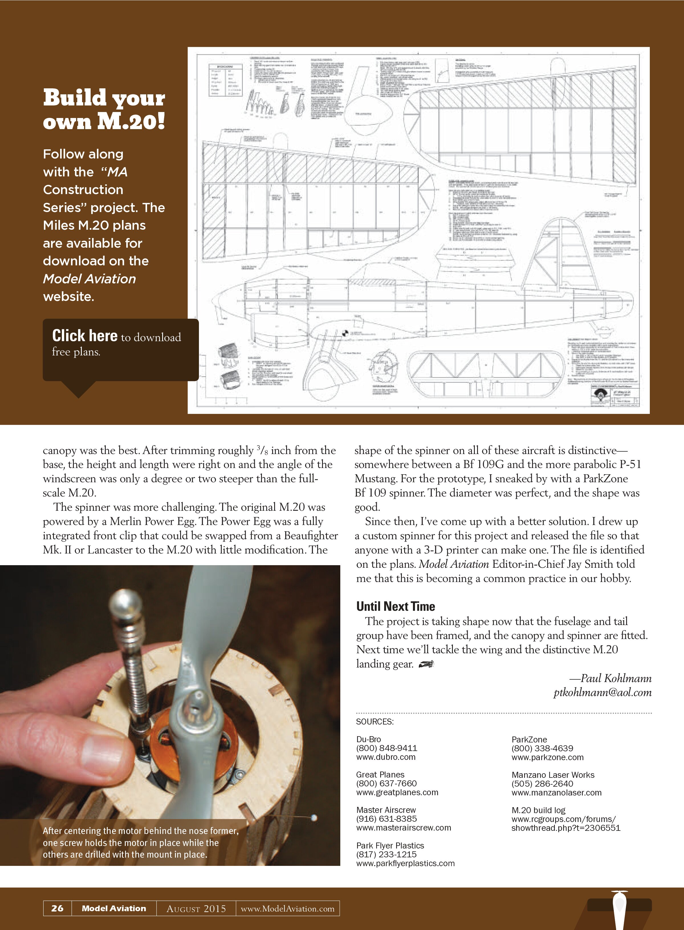
To install the motor, stand the fuselage on its tail. Set the motor with the X-mount attached to the face of the motor mount. Adjust the motor’s position so that it is centered in the fuselage opening. Mark the locations of the X-mount holes on the face of the motor mount.
I like to drill the first hole and run a hex-head screw through one corner of the X-mount. Now the motor’s position can be double checked before the other holes are drilled. Pivot the motor if necessary to improve the centering. If the first hole was off target, rotate the motor mount a few degrees and start over.
The face of the motor mount is usually made from plywood. The threads in the plywood can be strengthened with CA adhesive as was done with the balsa servo tray.
Plastics
Plastic is often the best material for parts such as canopies, spinners, and cowlings. These parts may be included in a kit, but builders who are working from a set of plans might have to be more creative. If parts for their specific plans are available, they can be purchased. If not, builders can form their own parts.
This isn’t as difficult as it may sound, but creating plugs and the forming process would fill another article or two. Finally, builders can adapt parts from other sources. For the M.20, I went with the third option.
Locating the right canopy was simple. There are several sources for plastic parts and one of the more notable is Park Flyer Plastics operated by Keith Sparks. Sparky’s website displays dozens of canopies with photos and dimensions. Several were close enough for the M.20, but the C70 Sea Fury


canopy was the best. After trimming roughly ⅜ inch from the base, the height and length were right on and the angle of the windscreen was only a degree or two steeper than the full-scale M.20.
The spinner was more challenging. The original M.20 was powered by a Merlin Power Egg. The Power Egg was a fully integrated front clip that could be swapped from a Beaufighter Mk. II or Lancaster to the M.20 with little modification. The

shape of the spinner on all of these aircraft is distinctive—somewhere between a Bf 109G and the more parabolic P-51 Mustang. For the prototype, I sneaked by with a ParkZone Bf 109 spinner. The diameter was perfect, and the shape was good.
Since then, I’ve come up with a better solution. I drew up a custom spinner for this project and released the file so that anyone with a 3-D printer can make one. The file is identified on the plans. Model Aviation Editor-in-Chief Jay Smith told me that this is becoming a common practice in our hobby.
Until Next Time
The project is taking shape now that the fuselage and tail group have been framed, and the canopy and spinner are fitted. Next time we’ll tackle the wing and the distinctive M.20 landing gear.
—Paul Kohlmann
ptkohlmann@aol.com
SOURCES:
Du-Bro
(800) 848-9411
www.dubro.com
Great Planes
(800) 637-7660
www.greatplanes.com
Master Airscrew
(916) 631-8385
www.masterairscrew.com
Park Flyer Plastics
(817) 233-1215
www.parkflyerplastics.com
ParkZone
(800) 338-4639
www.parkzone.com
Manzano Laser Works
(505) 286-2640
www.manzanolaser.com
M.20 build log
www.rcgroups.com/forums/
showthread.php?t=2306551