PRECISION AEROBATICS XR-52 ARF
Geoff Barber
gbarber726@gmail.com
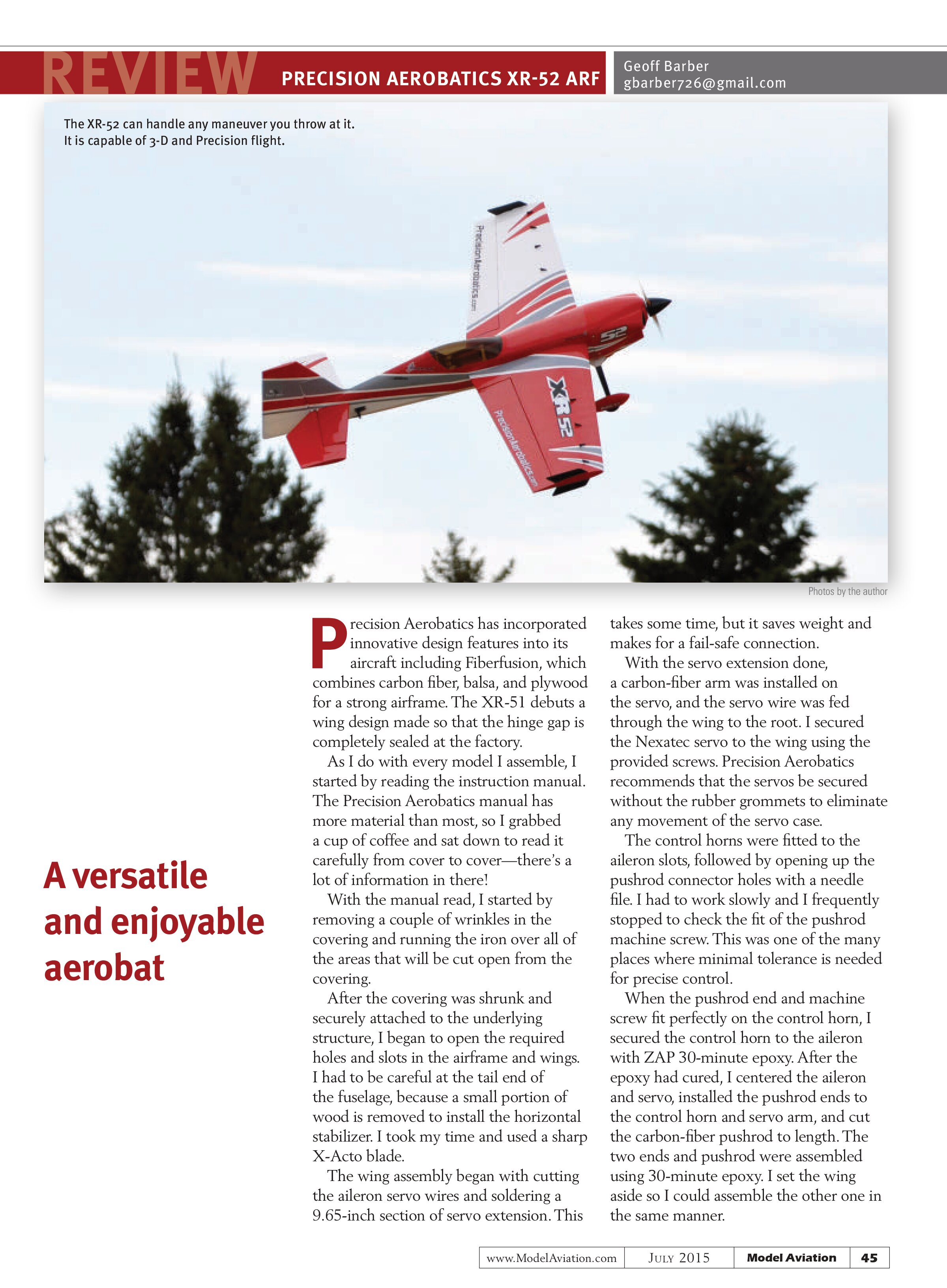
The XR-52 can handle any maneuver you throw at it.
It is capable of 3-D and Precision flight.

A versatile
and enjoyable
aerobat
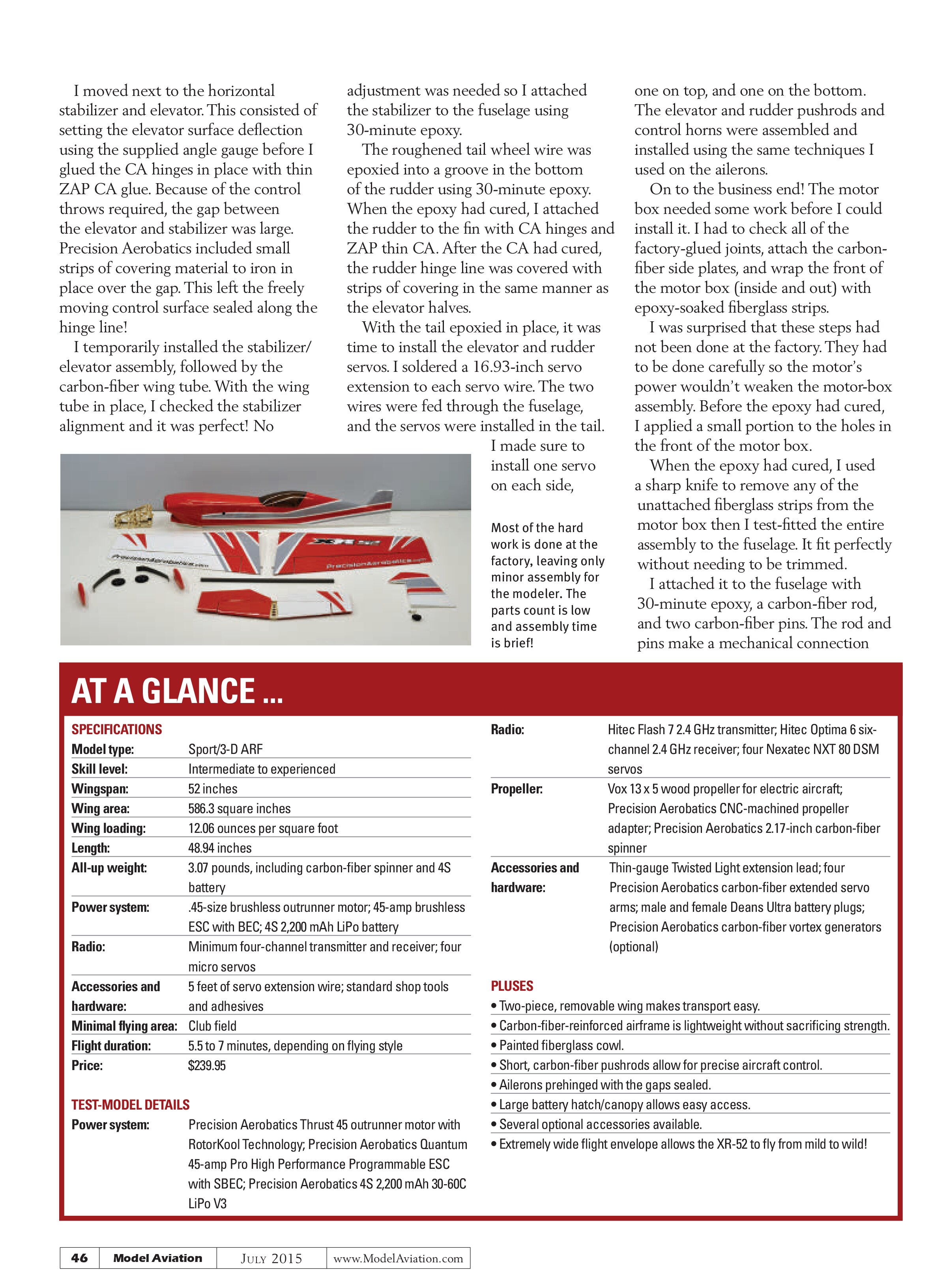
Precision Aerobatics has incorporated innovative design features into its aircraft including Fiberfusion, which combines carbon fiber, balsa, and plywood for a strong airframe. The XR-51 debuts a wing design made so that the hinge gap is completely sealed at the factory.
As I do with every model I assemble, I started by reading the instruction manual. The Precision Aerobatics manual has more material than most, so I grabbed a cup of coffee and sat down to read it carefully from cover to cover—there’s a lot of information in there!
With the manual read, I started by removing a couple of wrinkles in the covering and running the iron over all of the areas that will be cut open from the covering.
After the covering was shrunk and securely attached to the underlying structure, I began to open the required holes and slots in the airframe and wings. I had to be careful at the tail end of the fuselage, because a small portion of wood is removed to install the horizontal stabilizer. I took my time and used a sharp X-Acto blade.
The wing assembly began with cutting the aileron servo wires and soldering a 9.65-inch section of servo extension. This takes some time, but it saves weight and makes for a fail-safe connection.
With the servo extension done, a carbon-fiber arm was installed on the servo, and the servo wire was fed through the wing to the root. I secured the Nexatec servo to the wing using the provided screws. Precision Aerobatics recommends that the servos be secured without the rubber grommets to eliminate any movement of the servo case.
The control horns were fitted to the aileron slots, followed by opening up the pushrod connector holes with a needle file. I had to work slowly and I frequently stopped to check the fit of the pushrod machine screw. This was one of the many places where minimal tolerance is needed for precise control.
When the pushrod end and machine screw fit perfectly on the control horn, I secured the control horn to the aileron with ZAP 30-minute epoxy. After the epoxy had cured, I centered the aileron and servo, installed the pushrod ends to the control horn and servo arm, and cut the carbon-fiber pushrod to length. The two ends and pushrod were assembled using 30-minute epoxy. I set the wing aside so I could assemble the other one in the same manner.
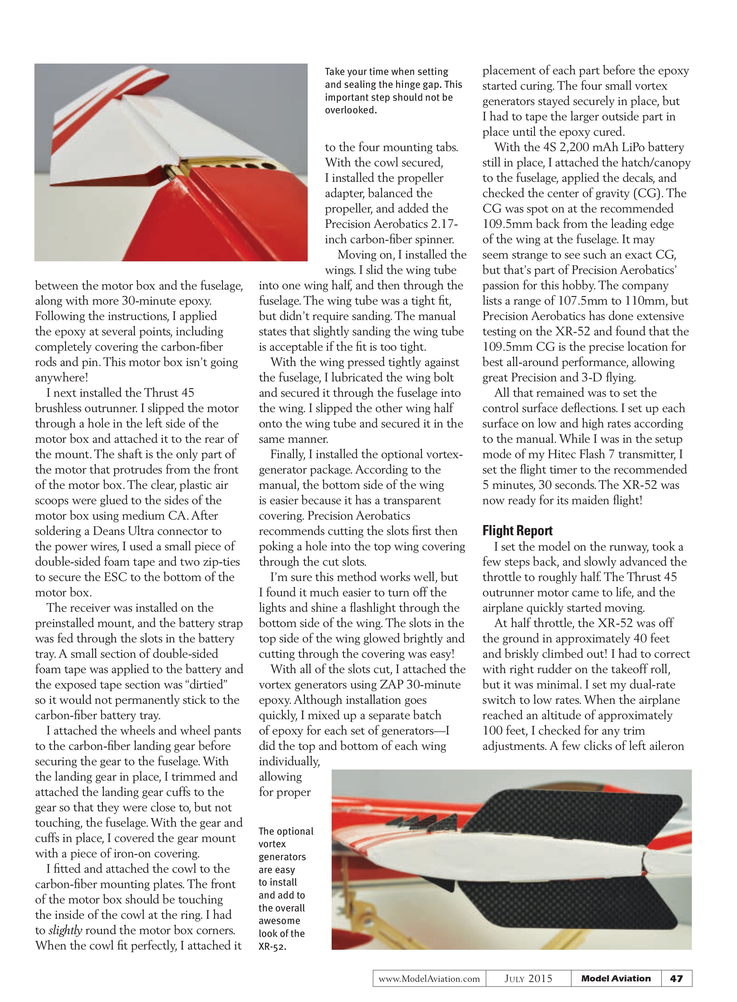
I moved next to the horizontal stabilizer and elevator. This consisted of setting the elevator surface deflection using the supplied angle gauge before I glued the CA hinges in place with thin ZAP CA glue. Because of the control throws required, the gap between the elevator and stabilizer was large. Precision Aerobatics included small strips of covering material to iron in place over the gap. This left the freely moving control surface sealed along the hinge line!
I temporarily installed the stabilizer/elevator assembly, followed by the carbon-fiber wing tube. With the wing tube in place, I checked the stabilizer alignment and it was perfect! No adjustment was needed so I attached the stabilizer to the fuselage using 30-minute epoxy.
The roughened tail wheel wire was epoxied into a groove in the bottom of the rudder using 30-minute epoxy. When the epoxy had cured, I attached the rudder to the fin with CA hinges and ZAP thin CA. After the CA had cured, the rudder hinge line was covered with strips of covering in the same manner as the elevator halves.
With the tail epoxied in place, it was time to install the elevator and rudder servos. I soldered a 16.93-inch servo extension to each servo wire. The two wires were fed through the fuselage, and the servos were installed in the tail. I made sure to install one servo on each side, one on top, and one on the bottom. The elevator and rudder pushrods and control horns were assembled and installed using the same techniques I used on the ailerons.
On to the business end! The motor box needed some work before I could install it. I had to check all of the factory-glued joints, attach the carbon-fiber side plates, and wrap the front of the motor box (inside and out) with epoxy-soaked fiberglass strips.
I was surprised that these steps had not been done at the factory. They had to be done carefully so the motor’s power wouldn’t weaken the motor-box assembly. Before the epoxy had cured, I applied a small portion to the holes in the front of the motor box.
When the epoxy had cured, I used a sharp knife to remove any of the unattached fiberglass strips from the motor box then I test-fitted the entire assembly to the fuselage. It fit perfectly without needing to be trimmed.
I attached it to the fuselage with 30-minute epoxy, a carbon-fiber rod, and two carbon-fiber pins. The rod and pins make a mechanical connection

AT A GLANCE ...
SPECIFICATIONS
Model type: Sport/3-D ARF
Skill level: Intermediate to experienced
Wingspan: 52 inches
Wing area: 586.3 square inches
Wing loading: 12.06 ounces per square foot
Length: 48.94 inches
All-up weight: 3.07 pounds, including carbon-fiber spinner and 4S battery
Power system: .45-size brushless outrunner motor; 45-amp brushless ESC with BEC; 4S 2,200 mAh LiPo battery
Radio: Minimum four-channel transmitter and receiver; four micro servos
Accessories and hardware: 5 feet of servo extension wire; standard shop tools and adhesives
Minimal flying area: Club field
Flight duration: 5.5 to 7 minutes, depending on flying style
Price: $239.95
TEST-MODEL DETAILS
Power system: Precision Aerobatics Thrust 45 outrunner motor with RotorKool Technology; Precision Aerobatics Quantum 45-amp Pro High Performance Programmable ESC with SBEC; Precision Aerobatics 4S 2,200 mAh 30-60C LiPo V3
Radio: Hitec Flash 7 2.4 GHz transmitter; Hitec Optima 6 six-channel 2.4 GHz receiver; four Nexatec NXT 80 DSM servos
Propeller: Vox 13 x 5 wood propeller for electric aircraft; Precision Aerobatics CNC-machined propeller adapter; Precision Aerobatics 2.17-inch carbon-fiber spinner
Accessories and hardware: Thin-gauge Twisted Light extension lead; four Precision Aerobatics carbon-fiber extended servo arms; male and female Deans Ultra battery plugs; Precision Aerobatics carbon-fiber vortex generators (optional)
PLUSES
- Two-piece, removable wing makes transport easy.
- Carbon-fiber-reinforced airframe is lightweight without sacrificing strength.
- Painted fiberglass cowl.
- Short, carbon-fiber pushrods allow for precise aircraft control.
- Ailerons prehinged with the gaps sealed.
- Large battery hatch/canopy allows easy access.
- Several optional accessories available.
- Extremely wide flight envelope allows the XR-52 to fly from mild to wild!
between the motor box and the fuselage, along with more 30-minute epoxy. Following the instructions, I applied the epoxy at several points, including completely covering the carbon-fiber rods and pin. This motor box isn’t going anywhere!
I next installed the Thrust 45 brushless outrunner. I slipped the motor through a hole in the left side of the motor box and attached it to the rear of the mount. The shaft is the only part of the motor that protrudes from the front of the motor box. The clear, plastic air scoops were glued to the sides of the motor box using medium CA. After soldering a Deans Ultra connector to the power wires, I used a small piece of double-sided foam tape and two zip-ties to secure the ESC to the bottom of the motor box.
The receiver was installed on the preinstalled mount, and the battery strap was fed through the slots in the battery tray. A small section of double-sided foam tape was applied to the battery and the exposed tape section was “dirtied” so it would not permanently stick to the carbon-fiber battery tray.
I attached the wheels and wheel pants to the carbon-fiber landing gear before securing the gear to the fuselage. With the landing gear in place, I trimmed and attached the landing gear cuffs to the gear so that they were close to, but not touching, the fuselage. With the gear and cuffs in place, I covered the gear mount with a piece of iron-on covering.
I fitted and attached the cowl to the carbon-fiber mounting plates. The front of the motor box should be touching the inside of the cowl at the ring. I had to slightly round the motor box corners. When the cowl fit perfectly, I attached it to the four mounting tabs.
With the cowl secured, I installed the propeller adapter, balanced the propeller, and added the Precision Aerobatics 2.17-inch carbon-fiber spinner.
Moving on, I installed the wings. I slid the wing tube into one wing half, and then through the fuselage. The wing tube was a tight fit, but didn’t require sanding. The manual states that slightly sanding the wing tube is acceptable if the fit is too tight.
With the wing pressed tightly against the fuselage, I lubricated the wing bolt and secured it through the fuselage into the wing. I slipped the other wing half onto the wing tube and secured it in the same manner.
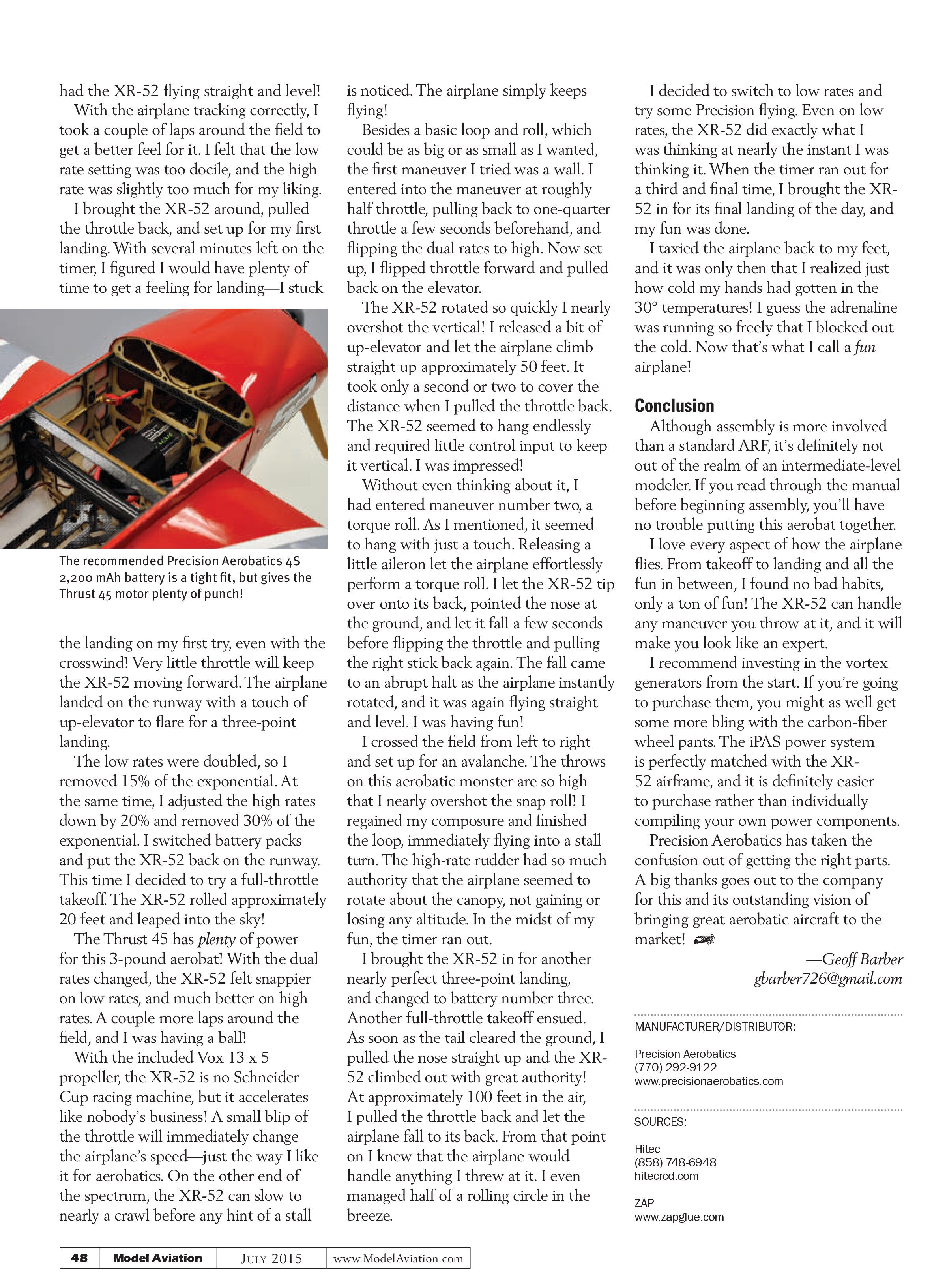
Finally, I installed the optional vortex-generator package. According to the manual, the bottom side of the wing is easier because it has a transparent covering. Precision Aerobatics recommends cutting the slots first then poking a hole into the top wing covering through the cut slots.
I’m sure this method works well, but I found it much easier to turn off the lights and shine a flashlight through the bottom side of the wing. The slots in the top side of the wing glowed brightly, and cutting through the covering was easy!
With all of the slots cut, I attached the vortex generators using ZAP 30-minute epoxy. Although installation goes quickly, I mixed up a separate batch of epoxy for each set of generators—I did the top and bottom of each wing individually, allowing for proper placement of each part before the epoxy started curing. The four small vortex generators stayed securely in place, but I had to tape the larger outside part in place until the epoxy cured.
With the 4S 2,200 mAh LiPo battery still in place, I attached the hatch/canopy to the fuselage, applied the decals, and checked the center of gravity (CG). The CG was spot on at the recommended 109.5mm back from the leading edge of the wing at the fuselage. It may seem strange to see such an exact CG, but that’s part of Precision Aerobatics’ passion for this hobby. The company lists a range of 107.5mm to 110mm, but Precision Aerobatics has done extensive testing on the XR-52 and found that the 109.5mm CG is the precise location for best all-around performance, allowing great Precision and 3-D flying.
All that remained was to set the control surface deflections. I set up each surface on low and high rates according to the manual. While I was in the setup mode of my Hitec Flash 7 transmitter, I set the flight timer to the recommended 5 minutes, 30 seconds. The XR-52 was now ready for its maiden flight!
Flight Report
I set the model on the runway, took a few steps back, and slowly advanced the throttle to roughly half. The Thrust 45 outrunner motor came to life, and the airplane quickly started moving.
At half throttle, the XR-52 was off the ground in approximately 40 feet and briskly climbed out! I had to correct with right rudder on the takeoff roll, but it was minimal. I set my dual-rate switch to low rates. When the airplane reached an altitude of approximately 100 feet, I checked for any trim adjustments. A few clicks of left aileron


had the XR-52 flying straight and level!
With the airplane tracking correctly, I took a couple of laps around the field to get a better feel for it. I felt that the low rate setting was too docile, and the high rate was slightly too much for my liking.
I brought the XR-52 around, pulled the throttle back, and set up for my first landing. With several minutes left on the timer, I figured I would have plenty of time to get a feeling for landing—I stuck

the landing on my first try, even with the crosswind! Very little throttle will keep the XR-52 moving forward. The airplane landed on the runway with a touch of up-elevator to flare for a three-point landing.
The low rates were doubled, so I removed 15% of the exponential. At the same time, I adjusted the high rates down by 20% and removed 30% of the exponential. I switched battery packs and put the XR-52 back on the runway. This time I decided to try a full-throttle takeoff. The XR-52 rolled approximately 20 feet and leaped into the sky!
The Thrust 45 has plenty of power for this 3-pound aerobat! With the dual rates changed, the XR-52 felt snappier on low rates, and much better on high rates. A couple more laps around the field, and I was having a ball!
With the included Vox 13 x 5 propeller, the XR-52 is no Schneider Cup racing machine, but it accelerates like nobody’s business! A small blip of the throttle will immediately change the airplane’s speed—just the way I like it for aerobatics. On the other end of the spectrum, the XR-52 can slow to nearly a crawl before any hint of a stall
is noticed. The airplane simply keeps flying!
Besides a basic loop and roll, which could be as big or as small as I wanted, the first maneuver I tried was a wall. I entered into the maneuver at roughly half throttle, pulling back to one-quarter throttle a few seconds beforehand, and flipping the dual rates to high. Now set up, I flipped throttle forward and pulled back on the elevator.
The XR-52 rotated so quickly I nearly overshot the vertical! I released a bit of up-elevator and let the airplane climb straight up approximately 50 feet. It took only a second or two to cover the distance when I pulled the throttle back. The XR-52 seemed to hang endlessly and required little control input to keep it vertical. I was impressed!
Without even thinking about it, I had entered maneuver number two, a torque roll. As I mentioned, it seemed to hang with just a touch. Releasing a little aileron let the airplane effortlessly perform a torque roll. I let the XR-52 tip over onto its back, pointed the nose at the ground, and let it fall a few seconds before flipping the throttle and pulling the right stick back again. The fall came to an abrupt halt as the airplane instantly rotated, and it was again flying straight and level. I was having fun!
I crossed the field from left to right and set up for an avalanche. The throws on this aerobatic monster are so high that I nearly overshot the snap roll! I regained my composure and finished the loop, immediately flying into a stall turn. The high-rate rudder had so much authority that the airplane seemed to rotate about the canopy, not gaining or losing any altitude. In the midst of my fun, the timer ran out.
I brought the XR-52 in for another nearly perfect three-point landing, and changed to battery number three. Another full-throttle takeoff ensued. As soon as the tail cleared the ground, I pulled the nose straight up and the XR-52 climbed out with great authority! At approximately 100 feet in the air, I pulled the throttle back and let the airplane fall to its back. From that point on I knew that the airplane would handle anything I threw at it. I even managed half of a rolling circle in the breeze.
I decided to switch to low rates and try some Precision flying. Even on low rates, the XR-52 did exactly what I was thinking at nearly the instant I was thinking it. When the timer ran out for a third and final time, I brought the XR-52 in for its final landing of the day, and my fun was done.
I taxied the airplane back to my feet, and it was only then that I realized just how cold my hands had gotten in the 30° temperatures! I guess the adrenaline was running so freely that I blocked out the cold. Now that’s what I call a fun airplane!
Conclusion
Although assembly is more involved than a standard ARF, it’s definitely not out of the realm of an intermediate-level modeler. If you read through the manual before beginning assembly, you’ll have no trouble putting this aerobat together.
I love every aspect of how the airplane flies. From takeoff to landing and all the fun in between, I found no bad habits, only a ton of fun! The XR-52 can handle any maneuver you throw at it, and it will make you look like an expert.
I recommend investing in the vortex generators from the start. If you’re going to purchase them, you might as well get some more bling with the carbon-fiber wheel pants. The iPAS power system is perfectly matched with the XR-52 airframe, and it is definitely easier to purchase rather than individually compiling your own power components.
Precision Aerobatics has taken the confusion out of getting the right parts. A big thanks goes out to the company for this and its outstanding vision of bringing great aerobatic aircraft to the market!
—Geoff Barber
gbarber726@gmail.com
MANUFACTURER/DISTRIBUTOR:
Precision Aerobatics
(770) 292-9122
www.precisionaerobatics.com
SOURCES:
Hitec
(858) 748-6948
hitecrcd.com