Small-Pack Slow Charger
By Bob Kopski
Background: Recent years have seen an explosion of interest in small Electrics. These "indoor" and "park flyers" have taken modeldom by storm! As probably the fastest growing interest area within aeromodeling, these smaller, lighter, quiet, and nonthreatening Radio Control (RC) Electrics are everywhere—because they can be. They even appear in television commercials for consumer products!
Power for these Electrics usually comes from small, rechargeable Ni-Cd and NiMH packs. These batteries have a rather broad range of cell count and milliampere-hour (mAh) capacity, and it's common for modelers to have several interchangeable packs for the same airplane. In addition, many fliers have multiple models, and these can use different packs.
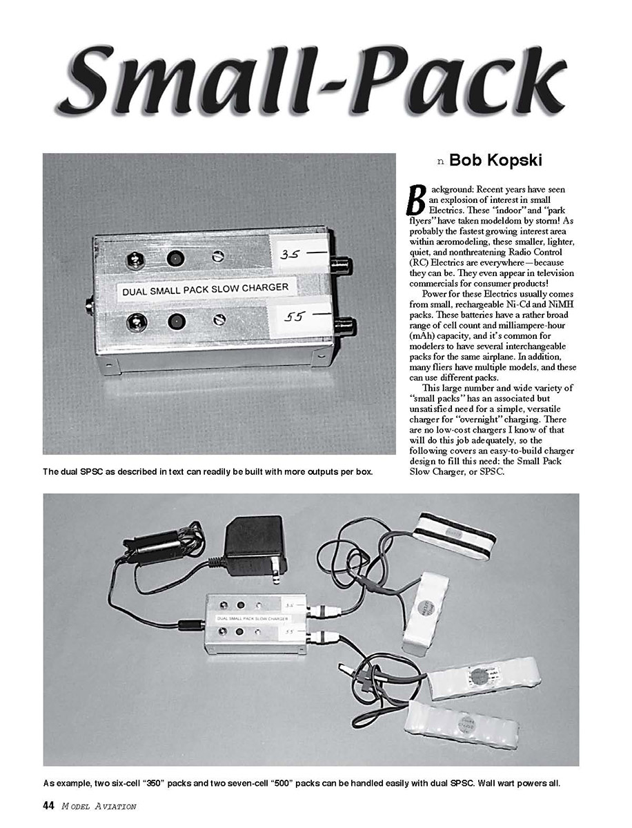
This large number and wide variety of "small packs" has an associated but unsatisfied need for a simple, versatile charger for "overnight" charging. There are no low-cost chargers I know of that will do this job adequately, so the following covers an easy-to-build charger design to fill this need: the Small Pack Slow Charger, or SPSC.
What It Is and What It Does:
Experienced Electric fliers often slow- or overnight-charge motor batteries for one of two reasons: to have packs ready for use or periodically to equalize cells within a pack for improved performance.
Common practice is to slow-charge at a rate of one-tenth capacity; i.e., the "C/10" rate. For example, a 100 mA pack would be charged at approximately 10 mA. A recommended duration is roughly 14 hours to assure maximum charge. The low-cost SPSC is especially designed to accomplish these things for all small packs.
The SPSC is based on a proven "constant current" regulator circuit (6/93 and 7/97 MA). As presented here, this circuit can charge one to at least 14 cells at any current between 5 mA and 75 mA. This covers the overnight-charging needs of 50 mAh through 750 mAh packs. This large range is achieved with smaller overlapping ranges of operation.
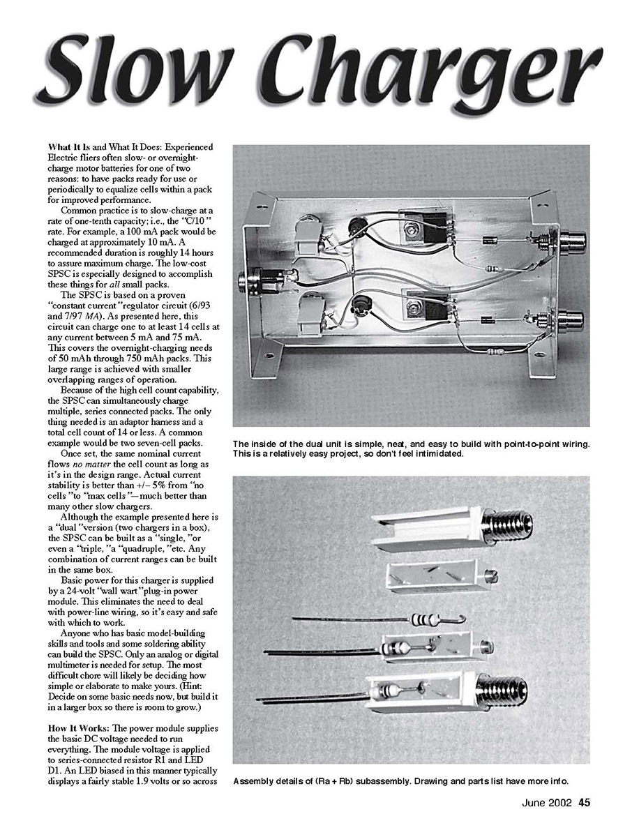
Because of the high cell count capability, the SPSC can simultaneously charge multiple, series connected packs. The only thing needed is an adaptor harness and a total cell count of 14 or less. A common example would be two seven-cell packs.
Once set, the same nominal current flows no matter the cell count as long as it's in the design range. Actual current stability is better than +/- 5% from "no cells" to "max cells" — much better than many other slow chargers.
Although the example presented here is a "dual" version (two chargers in a box), the SPSC can be built as a "single," or even a "triple," a "quadruple," etc. Any combination of current ranges can be built in the same box.
Basic power for this charger is supplied by a 24-volt "wall wart" plug-in power module. This eliminates the need to deal with power-line wiring, so it's easy and safe with which to work.
Anyone who has basic model-building skills and tools and some soldering ability can build the SPSC. Only an analog or digital multimeter is needed for setup. The most difficult chore will likely be deciding how simple or elaborate to make yours. (Hint: Decide on some basic needs now, but build it in a larger box so there is room to grow.)
How It Works: The power module supplies the basic DC voltage needed to run everything. The module voltage is applied to series-connected resistor R1 and LED D1. An LED biased in this manner typically displays a fairly stable 1.9 volts or so across its terminals. This voltage forms a reference at the base of PNP power transistor Q1.
The Q1 base-emitter junction drops approximately 0.6 volts in normal operation, so a fairly stable voltage of roughly 1.8 – 0.6 = 1.3 volts appears at the emitter. This voltage on emitter resistance (Ra + Rb) results in a stable emitter current. The actual voltage may differ slightly from unit to unit and throughout the operational range, but this does not matter.
Transistor collector current (the charger output current) is nearly equal to the emitter current, thus the charge current is primarily dependent on the emitter resistance value and is set by adjusting variable Ra. Also, this current is essentially independent of collector voltage. This is why the number of cells under charge does not matter — at least up to the design limit.
Because the transistor base appears as a high resistance across the LED during normal operation, the LED is an effective "charging" indicator. On the other hand, if no charge current is flowing, the transistor base no longer presents a high resistance to the LED circuit. Instead, LED current is robbed by the base, and the LED does not light. Therefore, the LED serves the dual purpose of regulating the output current and indicating when the charger is working properly.
Diode D2 serves to protect the pack and the charger if you have a pack in place but the wall wart is not plugged in. Note that it does not protect against connecting a pack backward; you must do your part here! Nothing will be damaged if you have too many cells connected, but charge current will not flow and the LED will not light, consequently indicating some problem.
Assembly, Application, and Adjustment Notes: The available current ranges are described on the assembly details drawing and in the parts list. Decide which current ranges are most suited to your needs and how many individual regulator circuits you want in one box. This will determine the range resistor selection and total parts count needed.
My "dual" uses one Range B and one Range C circuit. These are set to roughly 35 mA and 55 mA respectively for some present needs. I use the first for "350" packs and the second for "500" and "600" packs. In the latter case I compromised slightly on the classic C10 current value to conveniently cover both capacities.
The power module has a rated output of 400 mA. Essentially, all this is available for charging purposes since the internal circuitry only requires a few mA per regulator to function. When the "dual" cannot use all 400 mA, be mindful of this limitation if you build a version with more outputs.
The 20 turn trimmer resistors (Ra) have been chosen for electrical suitability and low cost. Rb sets the upper limit of range current consistent with the electrical rating of the associated trimmer, so stay with the combinations listed. You will find this approach mechanically and electrically very nice to use.
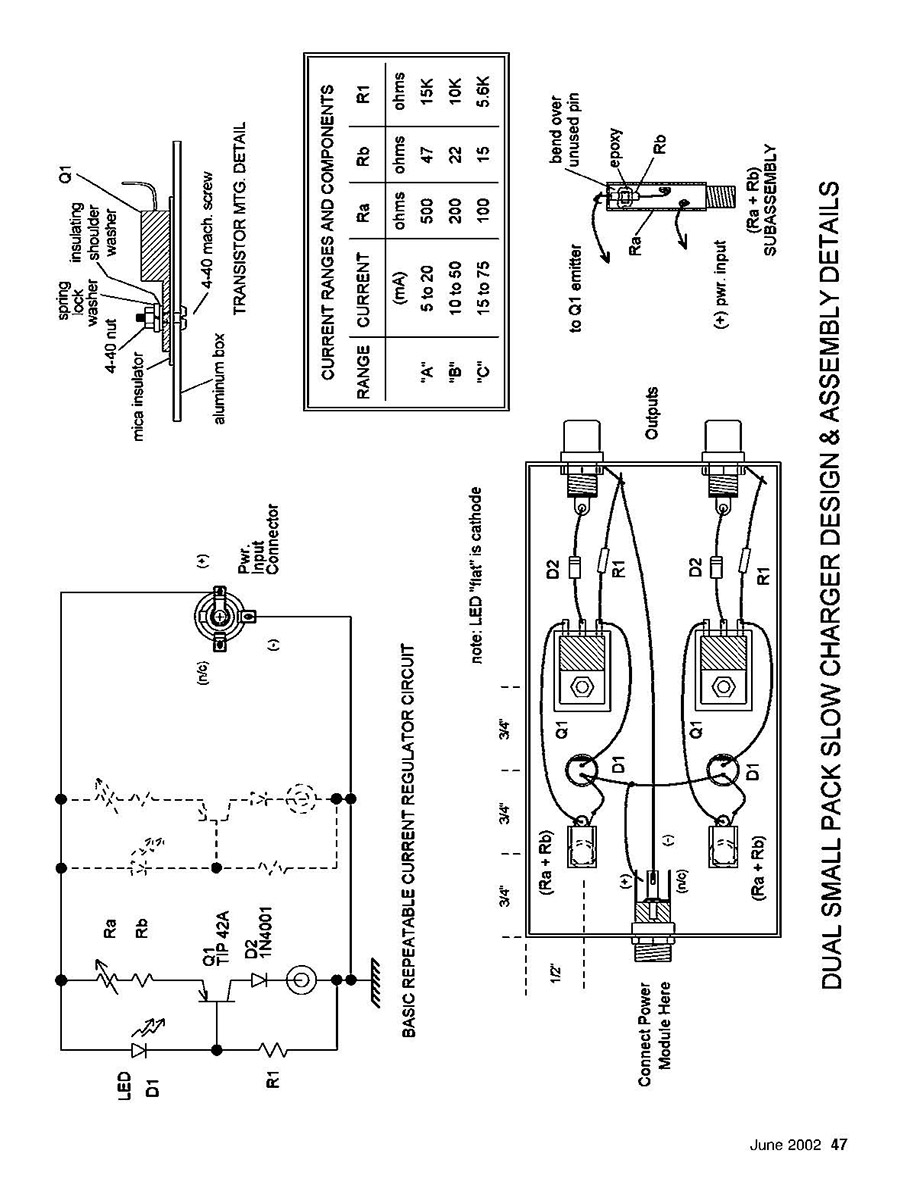
Rb is a 1/4-watt carbon resistor that is physically mounted on the associated (Ra) trimmer resistor. Solder one resistor lead to the middle pin of Ra as shown, and bend the unused pin of Ra over Rb as a sort of a holding clamp (makes sure it holds the resistor body and not a resistor lead).
Use a small drop of five-minute epoxy over the bent pin, the Rb body, and onto the Ra body to secure the whole works. This results in a "unitized" (Ra + Rb) subassembly. When cured, snap this unit into the matching mounts shown, to later be mounted on the box surface for easy access.
Ra is a screwdriver-adjusted resistor—a "set-and-forget" device; it is not intended to be a routine "adjustment pot". You can certainly readjust many times to accommodate different needs in time, but it is not designed to be constantly adjusted. It is described as having a limit-to-limit life of 200 cycles minimum.
Don't touch or adjust resistor R1 along with the range resistor (Ra + Rb).
The transistors are electrically insulated but thermally conductive to the aluminum box—absolutely necessary for proper electrical operation and thermal management. If you are building a larger version with more outputs, choose an aluminum box size such that each transistor has approximately six to eight square inches of metal for heatsinking purposes. Be generous with the area, especially for higher current versions.
When mounting transistor Q1, use the recommended TO-220 mounting hardware and possibly sand the metal back mounting surface a bit, burr-free, and otherwise quite smooth. I cannot emphasize this aspect enough! After a transistor is mounted but before it is wired into the circuit, confirm with an ohmmeter that there is no electrical connection between it and the metal box.
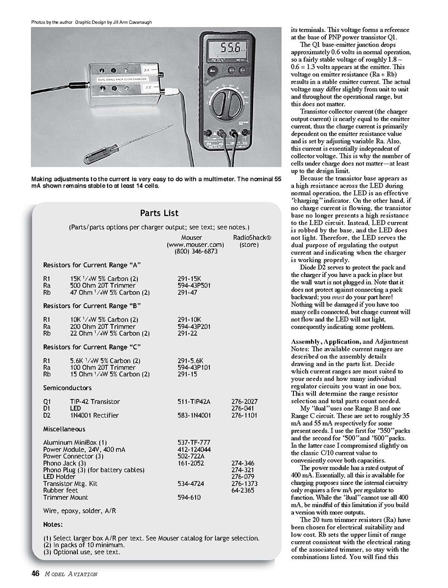
The charger assembly uses simple, point-to-point wiring. Some wiring might be done with the component leads directly. In the "dual", the LED-to-LED anode leads are connected. Be sure to dress any such connections to have some flex.
Other interconnections require wire; use 28- or 26-gauge, flexible, insulated wire. In particular, the connection points on the (Ra + Rb) subassembly are a little flimsy, so use care in wiring to these. Suitable wire includes the stripped from telephone handset cords and 22-26 RC wire.
My preference has always been to use phono connectors on all my cell chargers. This has proven to be low in cost and reliable. However, you are free to use other connector types you prefer.
You can permanently wire the small parts to the box or use a connector as shown. A connector permits use of the power module with other charger assemblies if you build more than one version.
Earlier I indicated that this design will charge to at least 14 cells. This is a minimum number, but the typical amount is greater. The "real" cell count limit is a variable because it depends on the power line voltage and the total charger current. At lower currents I'm normally able to charge as many as 18 cells per output of the "dual" for a grand total of 36!
This extra range comes about two ways. First, my home power line typically runs over 120 volts, so the basic power module output voltage is relatively high. Second, the power module output voltage is naturally higher at my way lower output currents. My "24-volt, 400 mA module" actually puts out more than 30 volts when used with my "dual".
You will know if you have too many cells connected: the LED will be off or very dim. One interesting aspect of this is that you can have a large cell count charging just fine—until it reaches near full charge. Then the battery voltage may rise just enough so that the charger current drops dramatically and the LED goes out.
This is a borderline cell count: you have "one cell too many". Two facts come into play here: good cells under slow charge normally reach a terminal voltage of roughly 1.55 volts when full, and approximately 2.5 volts of the module voltage is needed to operate the internal charger circuitry, but the rest is available for the battery. Some experimentation will define what you are able to do.
When you've completed your charger construction, be sure to inspect all your work for quality and accuracy—important for "smoke control!" When you are satisfied that it's well built with no errors, all that's left to do is operational checkout and output current adjustment. You can do this with a multimeter. You do not need any cells or packs for this step.
With the DC voltmeter function connected across the output, plug in the power module and observe roughly 28 to 32 volts (This varies with line voltage). Disconnect the voltmeter. Verify that the LED is now on and remains off throughout the complete adjustment range of Ra.
Decide on the current value you want, and select an appropriate current meter scale on the multimeter. Connect the current meter directly to the charger output. The LED should come on, and the meter should indicate some current.
Adjust the Ra screw for the current you want. It is normal for the current to change more quickly as the trimmers approach full CW rotation. Trimmer Ra may display some "backlash"; just be patient. Tune-up should only take a few minutes, and you're set for life—or until you get other packs with different charge current needs!
You may notice a small drift in output current for the first few minutes, especially when the highest currents are in use. This is because of warm-up. It's perfectly normal, and it will soon stabilize.
While it's normal for the box to run warm, the greatest heating will result from using the highest current with the fewest cells. This is the condition for least efficient operation, but at no time should temperature anywhere on the case reach the point where you are unable to touch it. This is only likely to occur for much larger versions, and if so, you have not used a large enough aluminum box.
If you want to impress your friends (and yourself), set a current with your meters in the preceding paragraph. Then connect a bunch of cells and the current meter in series with the output. You will see that the meter reading has hardly changed. This charger has a nearly constant output current—be it with zero cells (meter only) or the maximum number. It's a pretty good current source for all its low-cost simplicity!
Because I have many other chargers in use for many different batteries, I make the set current values on replaceable plastic tape with a Sharpie® marker. This is an easy way to prevent mix-ups and risky packs.
Remember that the aluminum box is at electrical "ground" potential; it's part of the circuit. This should never be a concern as long as exposed pack terminals and wiring thereto do not come in contact with the metal housing.
Astute readers may realize that one can actually parallel multiple charger outputs for higher currents. All that's needed is an external wiring harness that connects a single set of cells to the outputs. As set, my "dual" will deliver a paralleled current of roughly 90 mA—good for 1000 mAh packs!
Good luck with your Small-Pack Slow Charger. I like to hear from readers with project successes, so do send me a photo of your SPSC. On the other hand, I want to hear from readers who experience difficulty. Enclose a self-addressed, stamped envelope with your letter, and I will reply. I assure you that I will not let you fail if you give me the opportunity to help.
Happy small-electric flying, everyone! — Bob Kopski 25 West End Dr. Lansdale PA 19446
Parts List
(Parts/parts options per charger output; see text; see notes.)
Mouser (www.mouser.com) (800) 346-6873 RadioShack® (store)
Resistors for Current Range "A" R1 15K 1/4W 5% Carbon (2) — 291-15K Ra 500 Ohm 20T Trimmer — 594-43P501 Rb 47 Ohm 1/4W 5% Carbon (2) — 291-47
Resistors for Current Range "B" R1 10K 1/4W 5% Carbon (2) — 291-10K Ra 200 Ohm 20T Trimmer — 594-43P201 Rb 22 Ohm 1/4W 5% Carbon (2) — 291-22
Resistors for Current Range "C" R1 5.6K 1/4W 5% Carbon (2) — 291-5.6K Ra 100 Ohm 20T Trimmer — 594-43P101 Rb 15 Ohm 1/4W 5% Carbon (2) — 291-15
Semiconductors Q1 TIP-42 Transistor — 511-TIP42A / 276-2027 D1 LED — 276-041 D2 1N4001 Rectifier — 583-1N4001 / 276-1101
Miscellaneous Aluminum MiniBox (1) — 537-TF-777 Power Module, 24V, 400 mA — 412-120444 Power Connector (3) — 502-722A Phono Jack (3) — 161-2052 / 274-346 Phono Plug (3) (for battery cables) — 274-321 LED Holder — 276-079 Transistor Mgt. Kit — 534-4724 / 276-1373 Rubber feet — 64-2365 Trimmer Mount — 594-610
Wire, epoxy, solder, A/R
Notes: (1) Select larger box A/R per text. See Mouser catalog for large selection. (2) In packs of 10 minimum. (3) Optional use; see text.
TRANSISTOR MTG. DETAIL
mica insulator washer spring insulating sleeve washer 4-40 mach. screw 4-40 nut aluminum box Q1
CURRENT RANGES AND COMPONENTS
RANGE CURRENT (mA) R1 ohms Rb ohms Ra ohms "A" 5 to 20 15K 47 500 "B" 10 to 50 10K 22 200 "C" 15 to 75 5.6K 15 100
BASIC REPEATABLE CURRENT REGULATOR CIRCUIT
note: LED "flat" is cathode
LED D1 Ra Rb R1 Q1 TIP-42A D2 1N4001
(illustration of circuit connections)
DUAL SMALL PACK SLOW CHARGER DESIGN & ASSEMBLY DETAILS
Connect Power Module Here
1/2" 3/4" 3/4" 3/4"
Outputs
(to Q1 emitter) (+) pwr. input
(Ra + Rb) SUBASSEMBLY
(Ra + Rb)
(to Q1 emitter)
(Ra + Rb)
(Ra + Rb) (to outputs)
(note: LED "flat" is cathode)
Transcribed from original scans by AI. Minor OCR errors may remain.