House of Balsa Micro Electric Cub
Pros:
- Simple, efficient construction; easy and fun to build
- Excellent laser-cutting and parts fit
- Good plan and instructions with many photos
- Good flight performance with AstroFlight brushless 010
Cons:
- Nothing to dislike
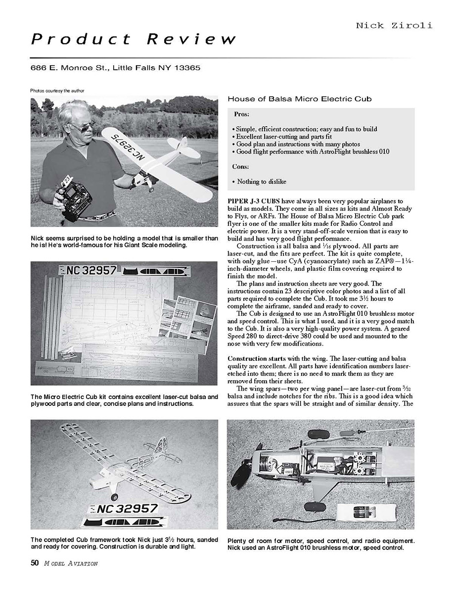
PIPER J-3 CUBS have always been very popular airplanes to build as models. They come in all sizes as kits and Almost Ready to Flys, or ARFs. The House of Balsa Micro Electric Cub park flyer is one of the smaller kits made for Radio Control and electric power. It is a very stand-off-scale version that is easy to build and has very good flight performance.
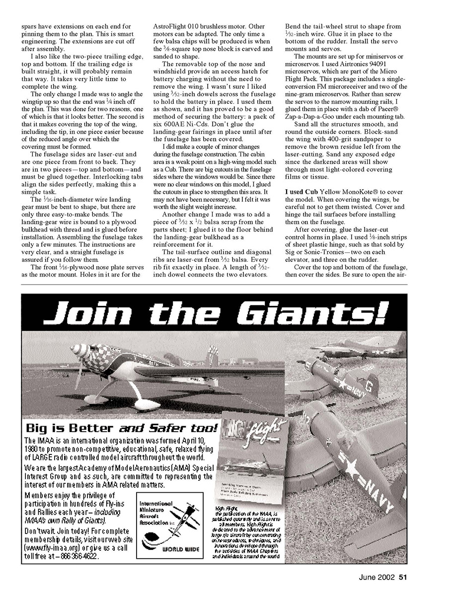
Construction is all balsa and 1/16 plywood. All parts are laser-cut, and the fits are perfect. The kit is quite complete, with only glue—use CyA (cyanoacrylate) adhesives such as ZAP®—1-1/4-inch-diameter wheels, and plastic film covering required to finish the model.
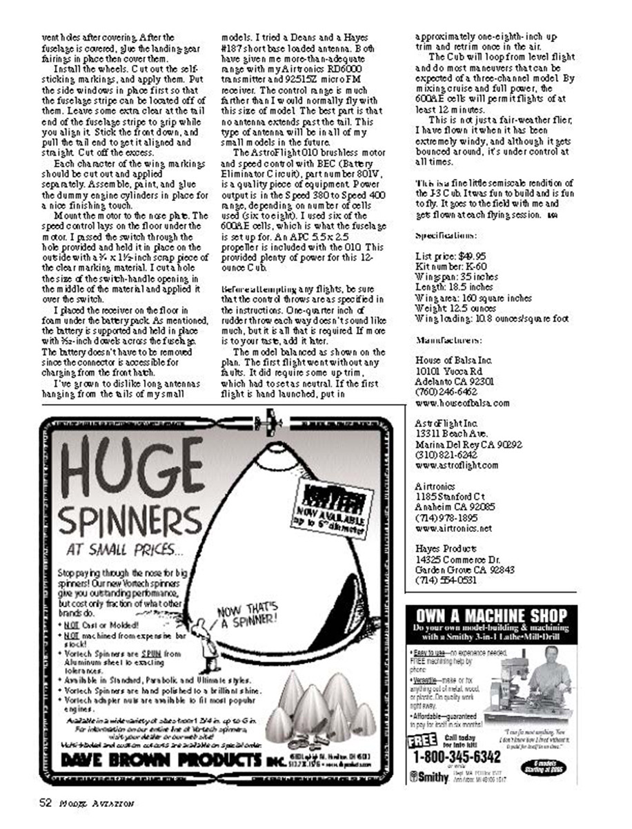
The plans and instruction sheets are very good. The instructions contain 23 descriptive color photos and a list of all parts required to complete the Cub. It took me 3-1/2 hours to complete the airframe, sanded and ready to cover.
The Cub is designed to use an AstroFlight 010 brushless motor and speed control. This is what I used, and it is a very good match to the Cub. It is also a very high-quality power system. A geared Speed 280 to direct-drive 380 could be used and mounted to the nose with very few modifications.
Construction starts with the wing. The laser-cutting and balsa quality are excellent. All parts have identification numbers laser-etched into them; there is no need to mark them as they are removed from their sheets.
The wing spars—two per wing panel—are laser-cut from 3/32 balsa and include notches for the ribs. This is a good idea which assures that the spars will be straight and of similar density. The spars have extensions on each end for pinning them to the plan. This is smart engineering. The extensions are cut off after assembly.
I also like the two-piece trailing edge, top and bottom. If the trailing edge is built straight, it will probably remain that way. It takes very little time to complete the wing.
The only change I made was to angle the wingtip up so that the end was 1/4 inch off the plan. This was done for two reasons, one of which is that it looks better. The second is that it makes covering the top of the wing, including the tip, in one piece easier because of the reduced angle over which the covering must be formed.
The fuselage sides are laser-cut and are one piece from front to back. They are in two pieces—top and bottom—and must be glued together. Interlocking tabs align the sides perfectly, making this a very simple task.
The 1/16-inch-diameter wire landing gear must be bent to shape, but there are only three easy-to-make bends. The landing-gear wire is bound to a plywood bulkhead with thread and is glued before installation. Assembling the fuselage takes only a few minutes. The instructions are very clear, and a straight fuselage is assured if you follow them.
The front 1/16-plywood nose plate serves as the motor mount. Holes in it are for the AstroFlight 010 brushless motor. Other motors can be adapted. The only time a few balsa chips will be produced is when the 3/8-square top nose block is carved and sanded to shape.
The removable top of the nose and windshield provide an access hatch for battery charging without the need to remove the wing. I wasn't sure I liked using 3/32-inch dowels across the fuselage to hold the battery in place. I used them as shown, and it has proved to be a good method of securing the battery: a pack of six 200AE Ni-Cads. Don't glue the landing-gear fairings in place until after the fuselage has been covered.
I did make a couple of minor changes during the fuselage construction. The cabin area is a weak point on a high-wing model such as a Cub. There are big cutouts in the fuselage sides where the windows would be. Since there were no clear windows on this model, I glued the cutouts in place to strengthen this area. It may not have been necessary, but I felt it was worth the slight weight increase.
Another change I made was to add a piece of 3/32 x 1/2 balsa scrap from the parts sheet; I glued it to the floor behind the landing-gear bulkhead as a reinforcement for it.
The tail-surface outline and diagonal ribs are laser-cut from 3/32 balsa. Every rib fit exactly in place. A length of 3/32-inch dowel connects the two elevators.
Bend the tail-wheel strut to shape from .032-inch wire. Glue it in place to the bottom of the rudder. Install the servo mounts and servos.
The mounts are set up for miniservos or microservos. I used Airtronics 94091 microservos, which are part of the Micro Flight Pack. This package includes a single conversion FM microreceiver and two of the nine-gram microservos. Rather than screw the servos to the narrow mounting rails, I glued them in place with a dab of Pacer® Zap-a-Dap-a-Goo under each mounting tab.
Sand all the structures smooth, and round the outside corners. Block-sand the wing with 400-grit sandpaper to remove the brown residue left from the laser-cutting. Sand any exposed edge since the darkened areas will show through most light-colored covering films or tissue.
I used Cub Yellow MonoKote® to cover the model. When covering the wings, be careful not to get them twisted. Cover and hinge the tail surfaces before installing them on the fuselage.
After covering, glue the laser-cut control horns in place. I used 1/8-inch strips of sheet plastic hinge, such as that sold by Sig or Sonic-Tronics—two on each elevator, and three on the rudder.
Cover the top and bottom of the fuselage, then cover the sides. Be sure to open the air-vent holes after covering.
Product Review
After the fuselage is covered, glue the landing gear fairings in place then cover them.
Install the wheels. Cut out the self-sticking markings, and apply them. Put the side windows in place first so that the fuselage stripe can be located off of them. Leave some extra clear at the tail end of the fuselage stripe to grip while you align it. Stick the front down, and pull the tail end to get it aligned and straight. Cut off the excess.
Each character of the wing markings should be cut out and applied separately. Assemble, paint, and glue the dummy engine cylinders in place for a nice finishing touch.
Mount the motor to the nose plate. The speed control lays on the floor under the motor. I passed the switch through the hole provided and held it in place on the outside with a 2-1/2-inch scrap piece of the clear marking material. I cut a hole the size of the switch-handle opening in the middle of the material and applied it over the switch.
I placed the receiver on the floor in front under the battery pack. As mentioned, the battery is supported and held in place with 3/8-inch dowel across the fuselage. The battery doesn’t have to be removed since the connector is accessible for charging from the front hatch.
I’ve grown to dislike long antennas hanging from the tails of my small models. I tried a Deans and a Hayes #187 short base loaded antenna. Both have given me more-than-adequate range with my Airtronics RD6000 transmitter and 925152 micro FM receiver. The control range is much farther than I would normally fly with this size of model. The best part is that no antenna extends past the tail. This type of antenna will be in all of my small models in the future.
The AstroFlight 010 brushless motor and speed control with BEC (Battery Eliminator Circuit), part number 801V, is a quality piece of equipment. Power output is in the S speed 380 to Speed 400 range, depending on number of cells used (six to eight). I used six of the 600AE cells, which is what the fuselage is set up for. An APC 5.5 x 2.5 propeller is included with the 010. This provided plenty of power for this 12-ounce Cub.
Before attempting any flights, be sure that the control throws are as specified in the instructions. One-quarter inch of rudder throw each way doesn’t sound like much, but it is all that is required. If more is to your taste, add it later.
The model balanced as shown on the plan. The first flight went without any faults. It did require some up trim, which had to be set as neutral. If the first flight is hand launched, put in approximately one-eighth-inch up trim and retrim once in the air.
The Cub will loop from level flight and do most maneuvers that can be expected of a three-channel model. By mixing cruise and full power, the 600AE cells will permit flights of at least 12 minutes.
This is not just a fair-weather flier; I have flown it when it has been extremely windy, and although it gets bounced around, it is under control at all times.
This is a fine little semic-scale rendition of the J-3 Cub. It is fun to build and is fun to fly. It goes to the field with me and gets flown at each flying session.
Specifications:
- List price: $49.95
- Kit number: K-60
- Wingspan: 35 inches
- Length: 18.5 inches
- Wing area: 100 square inches
- Weight: 12.5 ounces
- Wing loading: 10.8 ounces/square foot
Manufacturers:
House of Balsa Inc. 10101 Yucca Rd Adelanto CA 92301 (760) 246-6462 www.houseofbalsa.com
AstroFlight Inc. 13311 Beach Ave. Marina Del Rey CA 90292 (310) 821-6242 www.astroflight.com
Airtronics 1185 Stanford Ct Anaheim CA 92085 (714) 978-1895 www.airtronics.net
Hayes Products 14325 Commerce Dr. Garden Grove CA 92843 (714) 534-0531
Transcribed from original scans by AI. Minor OCR errors may remain.