The Perfect Marriage: Powered Airplanes
Let your glider hitch a ride to thermal land
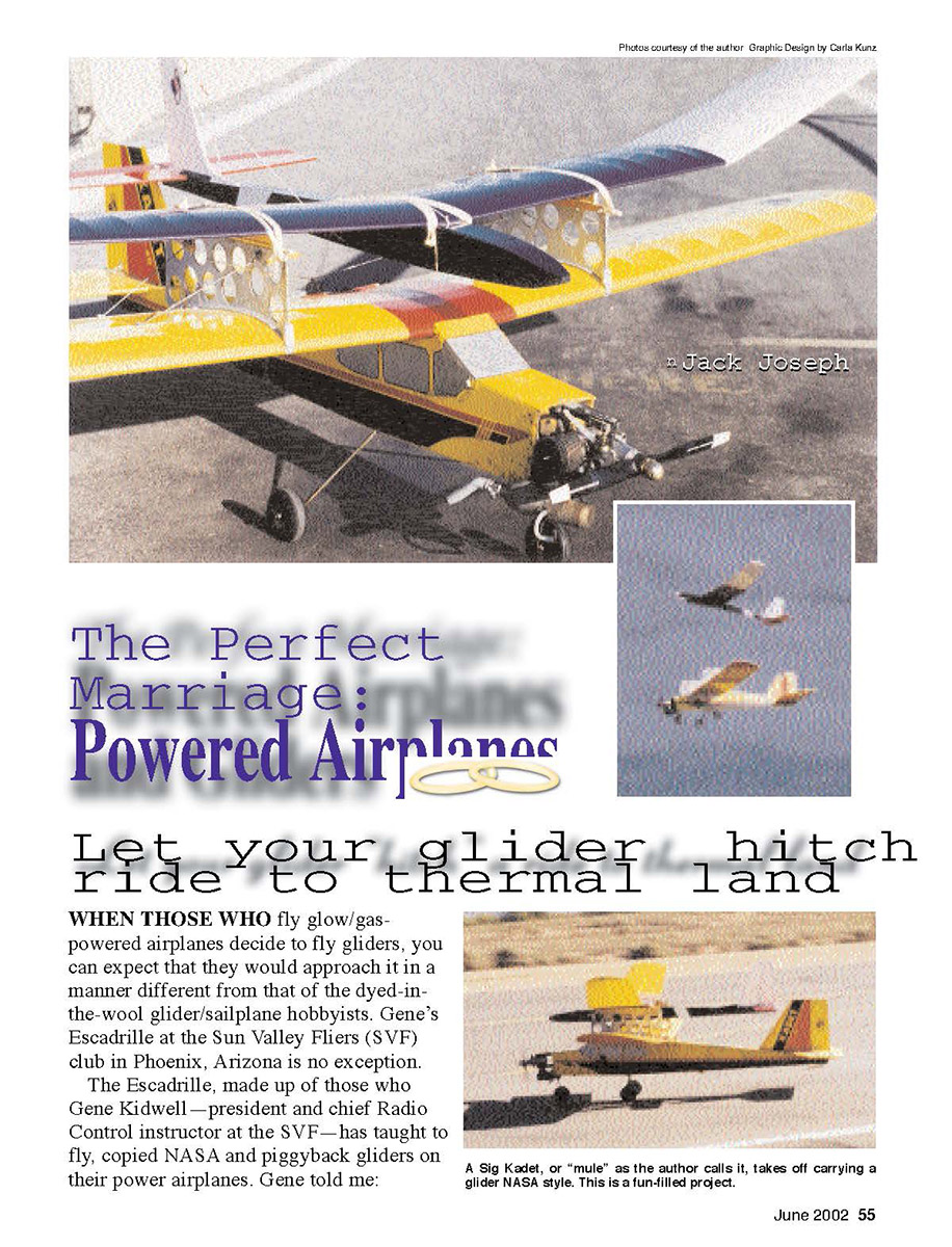
WHEN THOSE WHO fly glow/gas-powered airplanes decide to fly gliders, you can expect that they would approach it in a manner different from that of the dyed-in-the-wool glider/sailplane hobbyists. Gene's Escadrille at the Sun Valley Fliers (SVF) club in Phoenix, Arizona is no exception.
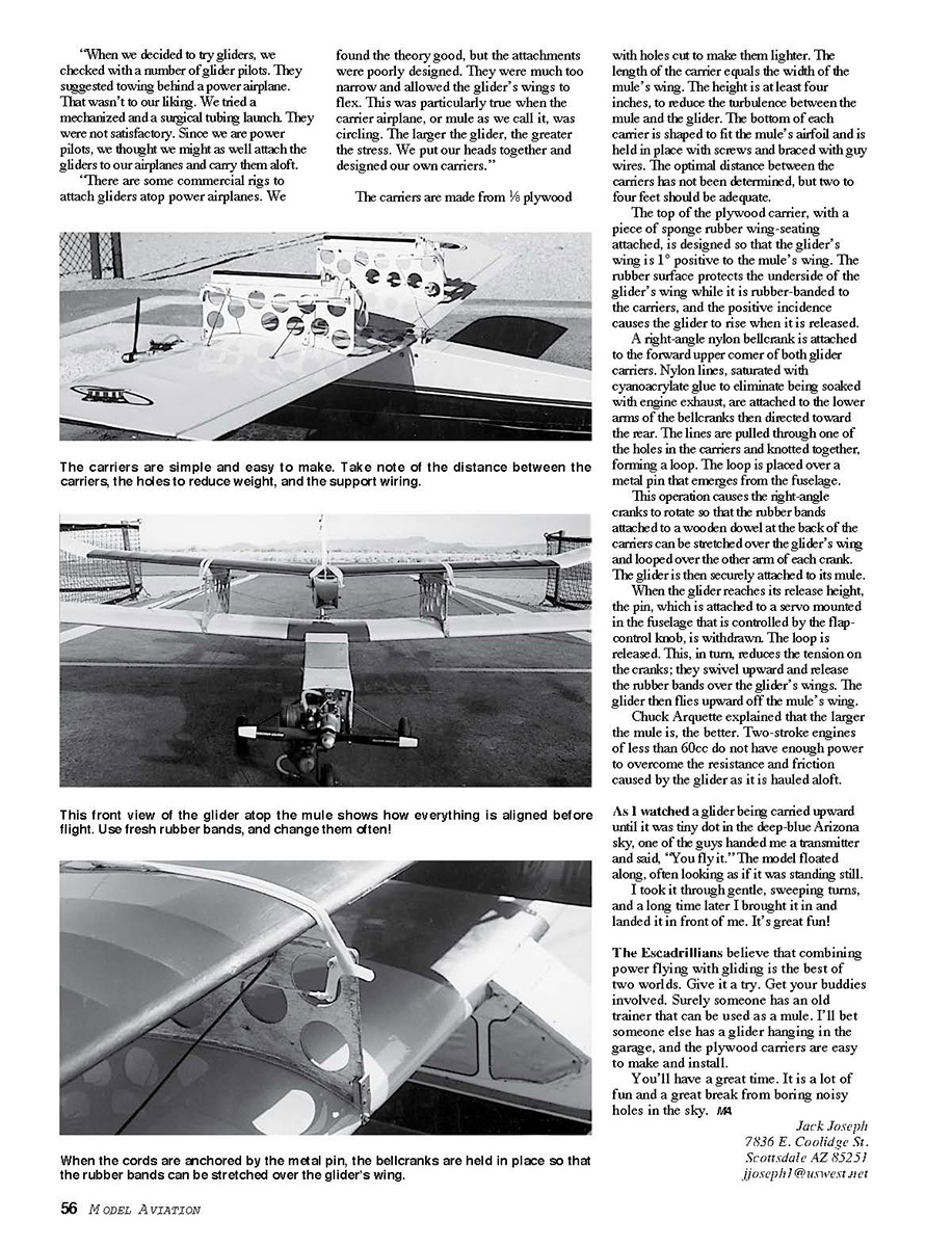
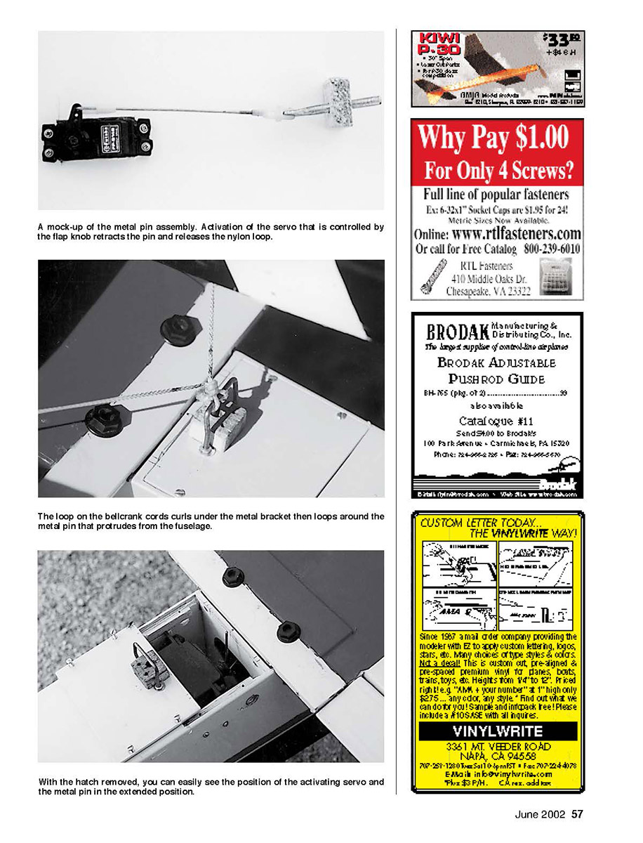
The Escadrille, made up of those who Gene Kidwell — president and chief Radio Control instructor at the SVF — has taught to fly, copied NASA and piggyback gliders on their power airplanes. Gene told me: "When we decided to try gliders, we checked with a number of glider pilots. They suggested towing behind a powered airplane. That wasn't to our liking. We tried a mechanized and a surgical tubing launch. They were not satisfactory. Since we are power pilots, we thought we might as well attach the gliders to our airplanes and carry them aloft.
"There are some commercial rigs to attach gliders atop power airplanes. We found the theory good, but the attachments were poorly designed. They were much too narrow and allowed the glider's wings to flex. This was particularly true when the carrier airplane, or mule as we call it, was circling. The larger the glider, the greater the stress. We put our heads together and designed our own carriers."
The carriers are made from 1/8 plywood with holes cut to make them lighter. The length of the carrier equals the width of the mule's wing. The height is at least four inches, to reduce the turbulence between the mule and the glider. The bottom of each carrier is shaped to fit the mule's airfoil and is held in place with screws and braced with guy wires. The optimal distance between the carriers has not been determined, but two to four feet should be adequate.
The top of the plywood carrier, with a piece of sponge rubber wing-seating attached, is designed so that the glider's wing is 1° positive to the mule's wing. The rubber surface protects the underside of the glider's wing while it is rubber-banded to the carriers, and the positive incidence causes the glider to rise when it is released.
A right-angle nylon bellcrank is attached to the forward upper corner of both glider carriers. Nylon lines, saturated with cyanoacrylate glue to eliminate being soaked with engine exhaust, are attached to the lower arms of the bellcranks then directed toward the rear. The lines are pulled through one of the holes in the carriers and knotted together, forming a loop. The loop is placed over a metal pin that emerges from the fuselage.
This operation causes the right-angle cranks to rotate so that the rubber bands attached to a wooden dowel at the back of the carriers can be stretched over the glider's wing and looped over the other arm of each crank. The glider is then securely attached to its mule.
When the glider reaches its release height, the pin, which is attached to a servo mounted in the fuselage that is controlled by the flap-control knob, is withdrawn. The loop is released. This, in turn, reduces the tension on the cranks; they swivel upward and release the rubber bands over the glider's wings. The glider then flies upward off the mule's wing.
Chuck Arquette explained that the larger the mule is, the better. Two-stroke engines of less than 60cc do not have enough power to overcome the resistance and friction caused by the glider as it is hauled aloft.
As I watched a glider being carried upward until it was tiny dot in the deep-blue Arizona sky, one of the guys handed me a transmitter and said, "You fly it." The model floated along, often looking as if it was standing still. I took it through gentle, sweeping turns, and a long time later I brought it in and landed it in front of me. It's great fun!
The Escadrillians believe that combining power flying with gliding is the best of two worlds. Give it a try. Get your buddies involved. Surely someone has an old trainer that can be used as a mule. I'll bet someone else has a glider hanging in the garage, and the plywood carriers are easy to make and install.
You'll have a great time. It is a lot of fun and a great break from boring noisy holes in the sky.
Jack Joseph <REDACTED> <REDACTED>
A mock-up of the metal pin assembly. Activation of the servo that is controlled by the flap knob retracts the pin and releases the nylon loop.
The loop on the bellcrank cords curls under the metal bracket then loops around the metal pin that protrudes from the fuselage.
With the hatch removed, you can easily see the position of the activating servo and the metal pin in the extended position.
Transcribed from original scans by AI. Minor OCR errors may remain.