Dewoitine D.338
Multiengine electric need not be difficult; this French transport is a logical starting point
by Laddie Mikulasko
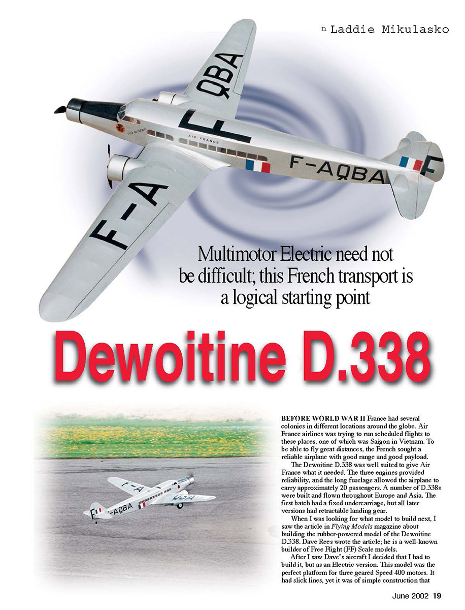
BEFORE WORLD WAR II France had several colonies in different locations around the globe. Air France was trying to run scheduled flights to these places, one of which was Saigon in Vietnam. To be able to fly great distances, the French sought a reliable airplane with good range and good payload.
The Dewoitine D.338 was well suited to give Air France what it needed. The three engines provided reliability, and the long fuselage allowed the airplane to carry approximately 20 passengers. A number of D.338s were built and flown throughout Europe and Asia. The first batch had a fixed undercarriage, but all later versions had retractable landing gear.
When I was looking for what model to build next, I saw the article in Flying Models magazine about building the rubber-powered model of the Dewoitine D.338. Dave Rees wrote the article; he is a well-known builder of Free Flight (FF) Scale models.
After I saw Dave’s aircraft I decided that I had to build it, but as an electric version. This model was the perfect platform for three geared Speed 400 motors. It had slick lines, yet it was of simple construction that could be easily duplicated on the model. From experience I knew that it could be a great flier.
I contacted Dave, and we decided to meet at an FF Scale meet at Geneseo in upstate New York. Dave gave me his complete documentation package to use. From this documentation I was able to make my own construction drawings. The outline of the model is as accurate as the three-view drawing I used. The tail surfaces might look small, but they are scale and more than adequate.
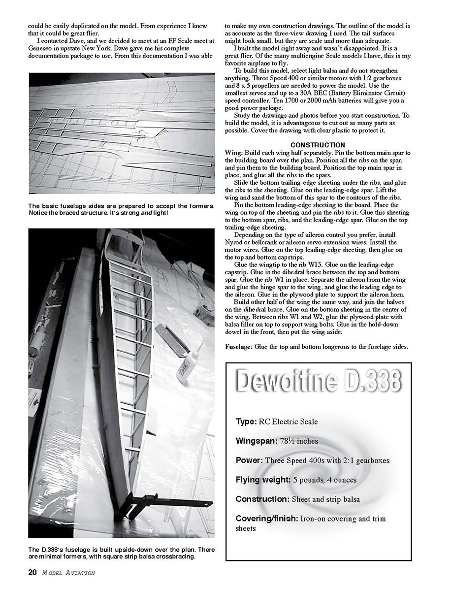
I built the model right away and wasn't disappointed. It is a great flier. Of the many multiengine Scale models I have, this is my favorite airplane to fly.
To build this model, select light balsa and do not strengthen anything. Three Speed 400 or similar motors with 1:2 gearboxes and 8 x 5 propellers are needed to power the model. Use the smallest servos and up to a 30A BEC (Battery Eliminator Circuit) speed controller. Ten 1700 or 2000 mAh batteries will give you a good power package.
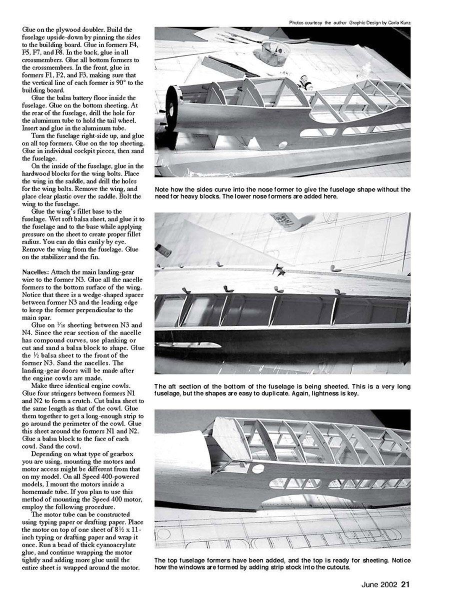
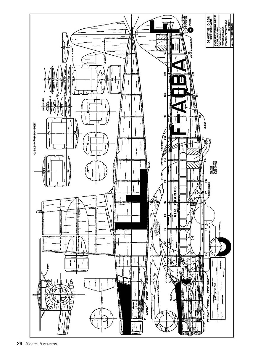
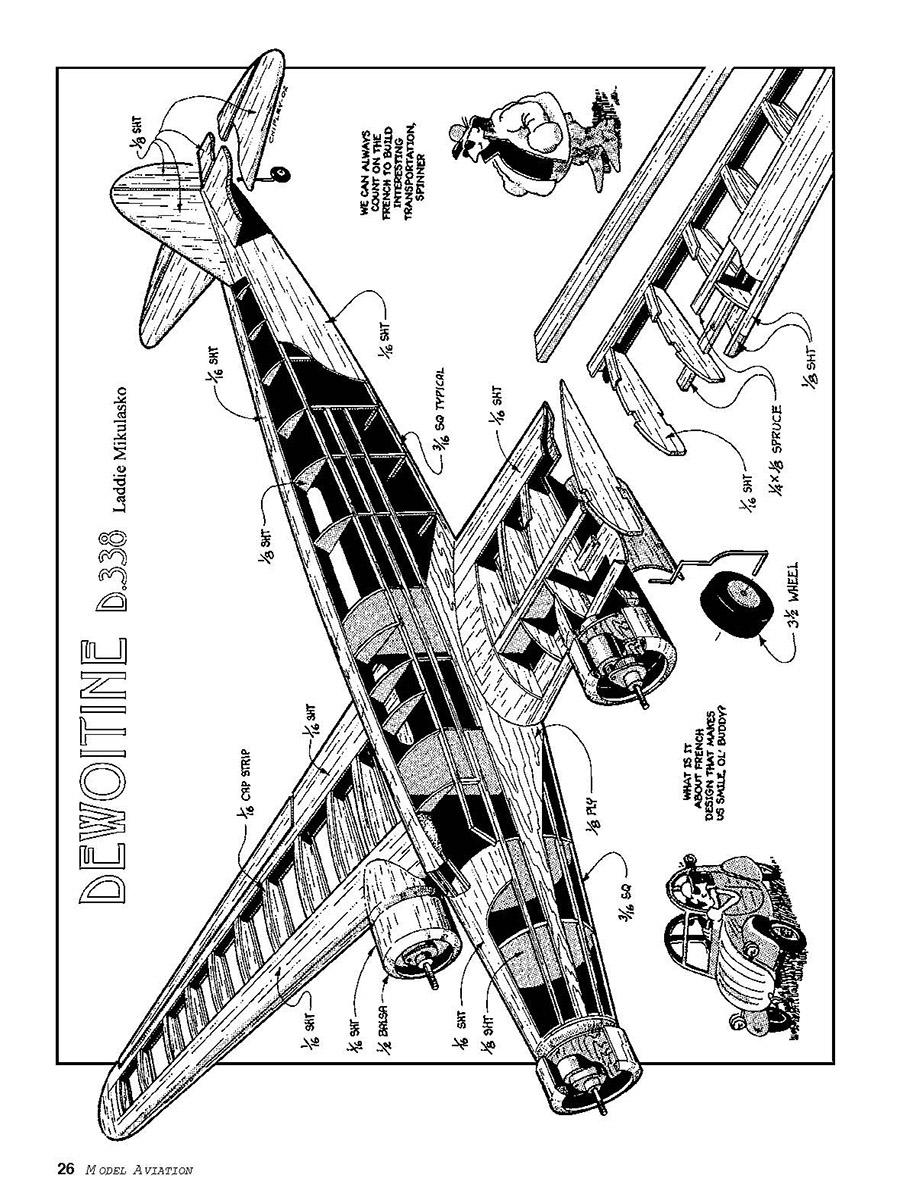
Study the drawings and photos before you start construction. To build the model, it is advantageous to cut out as many parts as possible. Cover the drawing with clear plastic to protect it.
CONSTRUCTION
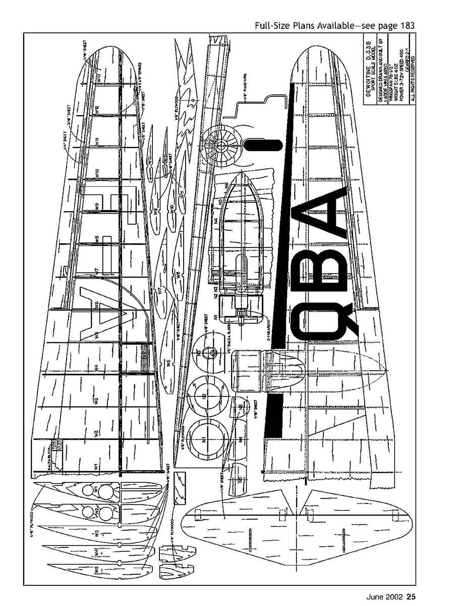
Wing: Build each wing half separately. Pin the bottom main spar to the building board over the plan. Position all the ribs on the spar, and pin them to the building board. Position the top main spar in place, and glue all the ribs to the spars.
Slide the bottom trailing-edge sheeting under the ribs, and glue the ribs to the sheeting. Glue on the leading-edge spar. Lift the wing and sand the bottom of this spar to the contours of the ribs.
Pin the bottom leading-edge sheeting to the board. Place the wing on top of the sheeting and pin the ribs to it. Glue this sheeting to the bottom spar, ribs, and the leading-edge spar. Glue on the top trailing-edge sheeting.
Depending on the type of aileron control you prefer, install Nyrod or bellcrank or aileron servo extension wires. Install the motor wires. Glue on the top leading-edge sheeting, then glue on the top and bottom capstrips.
Glue the wingtip to the rib W13. Glue on the leading-edge capstrip. Glue in the dihedral brace between the top and bottom spar. Glue the rib W1 in place. Separate the aileron from the wing and glue the hinge spar to the wing, and glue the leading edge to the aileron. Glue in the plywood plate to support the aileron horn.
Build the other half of the wing the same way, and join the halves on the dihedral brace. Glue on the bottom sheeting in the center of the wing. Between ribs W1 and W2, glue the plywood plate with balsa filler on top to support wing bolts. Glue in the hold-down dowel in the front, then put the wing aside.
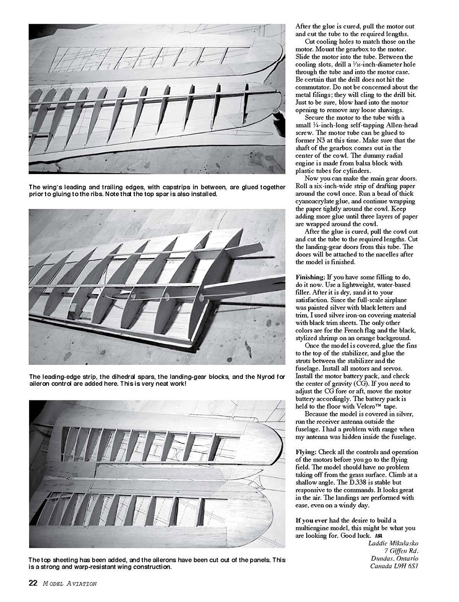
Fuselage: Glue the top and bottom longerons to the fuselage sides. Glue on the plywood doubler. Build the fuselage upside-down by pinning the sides to the building board. Glue in formers F4, F5, F7, and F8. In the back, glue in all crossmembers. Glue all bottom formers to the crossmembers. In the front, glue in formers F1, F2, and F3, making sure that the vertical line of each former is 90° to the building board.
Glue the balsa battery floor inside the fuselage. Glue on the bottom sheeting. At the rear of the fuselage, drill the hole for the aluminum tube to hold the tail wheel. Insert and glue in the aluminum tube.
Turn the fuselage right-side up, and glue on all top formers. Glue on the top sheeting. Glue in individual cockpit pieces, then sand the fuselage.
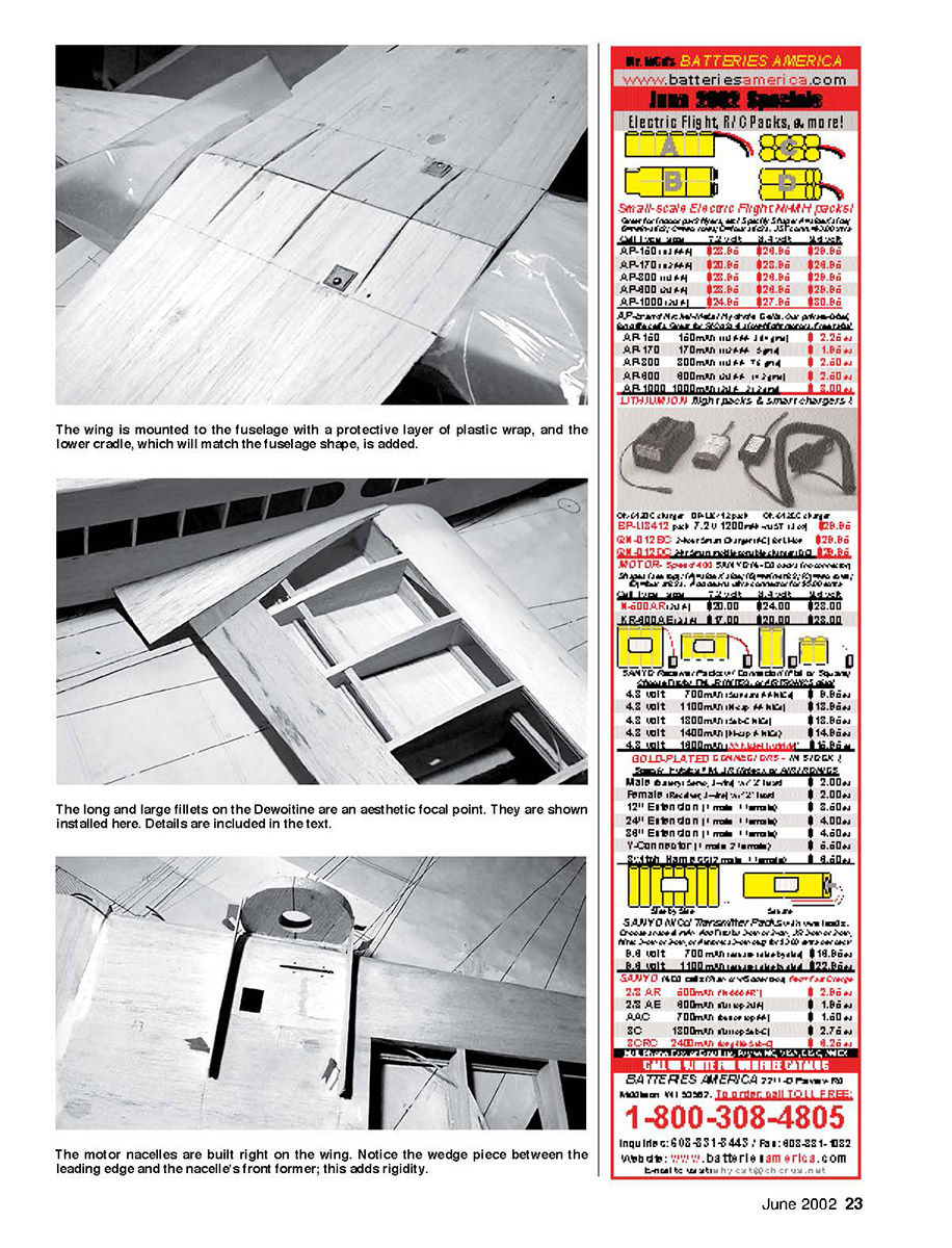
On the inside of the fuselage, glue in the hardwood blocks for the wing bolts. Place the wing in the saddle, and drill the holes for the wing bolts. Remove the wing, and place clear plastic over the saddle. Bolt the wing to the fuselage.
Glue the wing’s fillet base to the fuselage. Wet soft balsa sheet, and glue it to the fuselage and to the base while applying pressure on the sheet to create proper fillet radius. You can do this easily by eye. Remove the wing from the fuselage. Glue on the stabilizer and the fin.
Nacelles: Attach the main landing-gear wire to the former N3. Glue all the nacelle formers to the bottom surface of the wing. Notice that there is a wedge-shaped spacer between former N3 and the leading edge to keep the former perpendicular to the main spar.
Glue on 1/16 sheeting between N3 and N4. Since the rear section of the nacelle has compound curves, use planking or cut and sand a balsa block to shape. Glue the 1/2 balsa sheet to the front of the former N3. Sand the nacelles. The landing-gear doors will be made after the engine cowls are made.
Make three identical engine cowls. Glue four stringers between formers N1 and N2 to form a crutch. Cut balsa sheet to the same length as that of the cowl. Glue them together to get a long-enough strip to go around the perimeter of the cowl. Glue this sheet around the formers N1 and N2. Glue a balsa block to the face of each cowl. Sand the cowl.
Depending on what type of gearbox you are using, mounting the motors and motor access might be different from that on my model. On all Speed 400-powered models, I mount the motors inside a homemade tube. If you plan to use this method of mounting the Speed 400 motor, employ the following procedure.
The motor tube can be constructed using typing paper or drafting paper. Place the motor on top of one sheet of 8 1/2 x 11-inch typing or drafting paper and wrap it once. Run a bead of thick cyanoacrylate glue, and continue wrapping the motor tightly and adding more glue until the entire sheet is wrapped around the motor. After the glue is cured, pull the motor out and cut the tube to the required lengths.
Cut cooling holes to match those on the motor. Mount the gearbox to the motor. Slide the motor into the tube. Between the cooling slots, drill a 1/16-inch-diameter hole through the tube and into the motor case. Be certain that the drill does not hit the commutator. Do not be concerned about the metal filings; they will cling to the drill bit. Just to be sure, blow hard into the motor opening to remove any loose shavings.
Secure the motor to the tube with a small 1/4-inch-long self-tapping Allen-head screw. The motor tube can be glued to former N3 at this time. Make sure that the shaft of the gearbox comes out in the center of the cowl. The dummy radial engine is made from balsa block with plastic tubes for cylinders.
Now you can make the main gear doors.
Roll a six-inch-wide strip of drafting paper around the cowl once. Run a bead of thick cyanoacrylate glue, and continue wrapping the paper tightly around the cowl. Keep adding more glue until three layers of paper are wrapped around the cowl.
After the glue is cured, pull the cowl out and cut the tube to the required lengths. Cut the landing-gear doors from this tube. The doors will be attached to the nacelles after the model is finished.
Finishing: If you have some filling to do, do it now. Use a lightweight, water-based filler. After it is dry, sand it to your satisfaction. Since the full-scale airplane was painted silver with black letters and trim, I used silver iron-on covering material with black trim sheets. The only other colors are for the French flag and the black, stylized shrimp on an orange background.
Once the model is covered, glue the fins to the top of the stabilizer, and glue the struts between the stabilizer and the fuselage. Install all motors and servos. Install the motor battery pack, and check the center of gravity (CG). If you need to adjust the CG fore or aft, move the motor battery accordingly. The battery pack is held to the floor with Velcro tape.
Because the model is covered in silver, run the receiver antenna outside the fuselage. I had a problem with range when my antenna was hidden inside the fuselage.
Flying: Check all the controls and operation of the motors before you go to the flying field. The model should have no problem taking off from the grass surface. Climb at a shallow angle. The D.338 is stable but responsive to the commands. It looks great in the air. The landings are performed with ease, even on a windy day.
If you ever had the desire to build a multiengine model, this might be what you are looking for. Good luck.
Laddie Mikulasko 7 Giffin Rd. Dundas, Ontario Canada L9H 6S1
The wing is mounted to the fuselage with a protective layer of plastic wrap, and the lower cradle, which will match the fuselage shape, is added.
The long and large fillets on the Dewoitine are an aesthetic focal point. They are shown installed here. Details are included in the text.
The motor nacelles are built right on the wing. Notice the wedge piece between the leading edge and the nacelle's front former; this adds rigidity.
Transcribed from original scans by AI. Minor OCR errors may remain.