Kairos
Tom Dixon
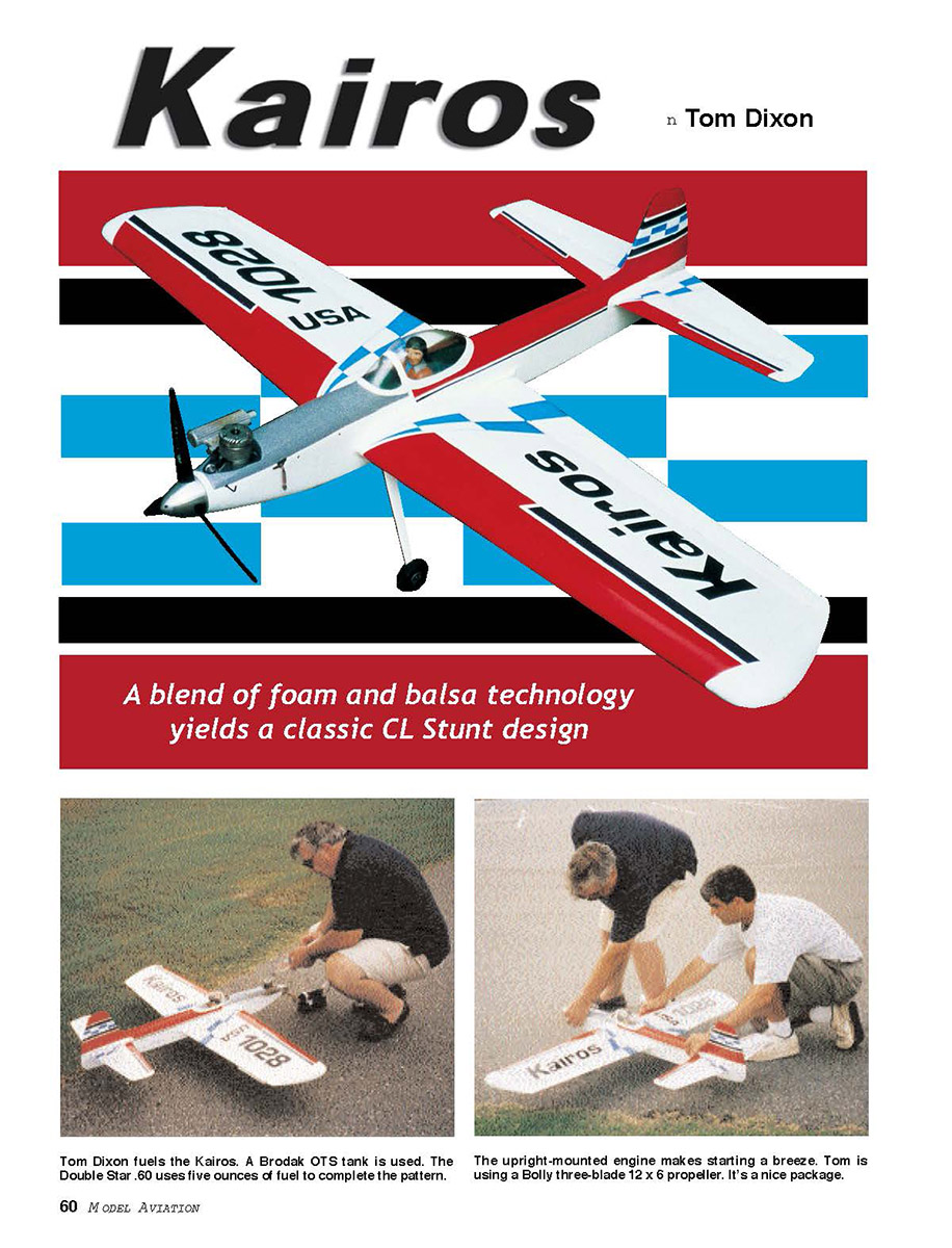
A blend of foam and balsa technology yields a classic CL Stunt design
Tradition can be paralyzing. Since the early 1950s there has been a tradition of sleekly cowled inverted engines in models in the Control Line (CL) Stunt event. They have resembled the classic inline 6s and V-12s of full-scale aviation's golden era of air racing and the sleek prop-driven fighters of World War II.
However, when you get down to it, mounting an engine with the cylinder down makes no sense. It is harder to start and can flood or even hydraulic-lock easily. It is not as safe; removing the starter battery is more difficult when one has to reach under the nose to get to it. Maintaining the engine and the tank is harder, requiring a work cradle or a blanket to support the model on its back while maintenance is performed.
All these difficulties have been tolerated through the years purely for aesthetic reasons—and the tradition of "We've (nearly) always done it that way."
The Kairos is a fully competitive CL Stunt model, which does make sense. It especially makes sense for beginner- to advanced-level fliers who need an easy-to-build, easy-to-fly, easy-to-maintain model on which to hone their skills. It also makes sense if you fly alone with a stooge; such a configuration is inherently safer to operate.
The aerodynamic layout is a derivation of my Time Machine design, itself a downsized version of Jim Greenaway's Pattern Master. The Kairos uses the Time Machine core but has slightly different wing and tail shapes and different-shaped tail surfaces.
The bubble canopy somewhat captures the look of an Su-31 or Yak-55 full-scale aerobatic design. The exact shape of any of these components doesn't matter much as long as the areas, moments, and alignments are maintained. Experiment with looks if you want.
Power in the original is a Double Star .60 Lite ringed engine. For the first six months I flew this design I had a worn-out engine but didn't realize it. I thought I had tank or fuel problems, and I put three different fuel tanks in the model and tried several fuels.
All the problems went away when I replaced the piston and sleeve (which were a mere five years old and had flown hundreds of flights) with a new ring setup. The engine was the original Double Star .60 to arrive in this country, so it had certainly done its duty. The steady engine runs finally allowed the model's full potential to show.
At the 2001 King Orange meet in Jacksonville FL the model finished fourth in a 15-person field, just behind Bill Rich, Randy Smith, and John Simpson, running the only wood propeller in the class. Figuring there may be something to this carbon-propeller stuff, I tried a Bolly 12 x 6 three-blade that had hung on my wall for two years. This propeller is the last piece of the puzzle; it gives proper speed without windup and lets the engine sound "just right."
If the model had had an inverted engine, I'd probably have trashed it after all the tank changing and so forth. Setting the model on its wheels for maintenance allowed me to get the combination right for outstanding performance before I lost my patience.
CONSTRUCTION
This airplane is quite easy to build. The foam-wing technique is very quick, accurate, and light. The tail surfaces are simple sheet balsa. The cowl is a piece of block with a hole cut in it for the cylinder to protrude through. The only thing that could be simpler would be to use a painted canopy, thereby eliminating the need for detailing or a pilot. Jim Svitko built his model this way for just these reasons.
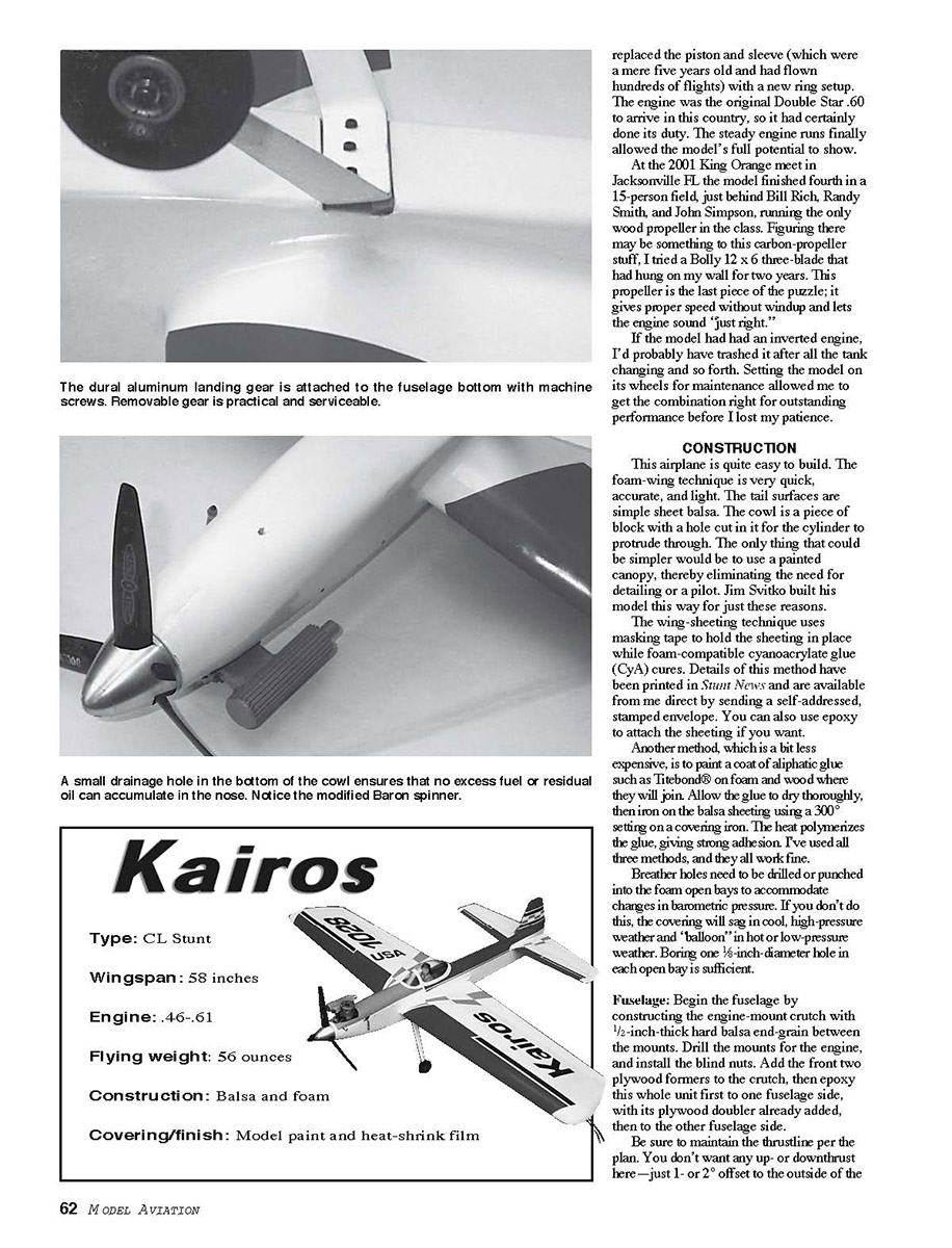
The wing-sheeting technique uses masking tape to hold the sheeting in place while foam-compatible cyanoacrylate glue (CyA) cures. Details of this method have been printed in Stunt News and are available from me direct by sending a self-addressed, stamped envelope. You can also use epoxy to attach the sheeting if you want.
Another method, which is a bit less expensive, is to paint a coat of aliphatic glue such as Titebond on foam and wood where they will join. Allow the glue to dry thoroughly, then iron on the balsa sheeting using a 300° setting on a covering iron. The heat polymerizes the glue, giving strong adhesion. I've used all three methods, and they all work fine.
Breather holes need to be drilled or punched into the foam open bays to accommodate changes in barometric pressure. If you don't do this, the covering will sag in cool, high-pressure weather and "balloon" in hot or low-pressure weather. Boring one 1/16-inch-diameter hole in each open bay is sufficient.
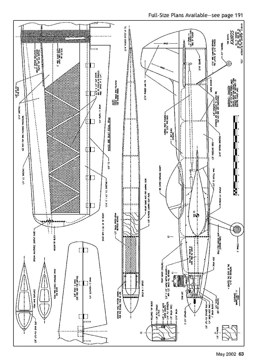
Fuselage: Begin the fuselage by constructing the engine-mount crutch with 1/2-inch-thick hard balsa end-grain between the mounts. Drill the mounts for the engine, and install the blind nuts. Add the front two plywood formers to the crutch, then epoxy this whole unit to one fuselage side, with its plywood doubler already added, then to the other fuselage side.
Be sure to maintain the thrustline per the plan. You don't want any up- or downthrust here—just 1- or 2° offset to the outside of the flying circle (which is done when you're drilling the mounts). Do not put the blind nuts to the top side of the fuselage out of habit!
The rear balsa formers should have the grain running from side to side, not up and down, for maximum stiffness. Be sure you have a symmetrical curve in both fuselage sides. If there is an error, it should be toward "right rudder."
Shape the cowl, top block, and bottom nose section before installing the wing. Remove the top block and cowl blocks, then hollow to approximately 3/16-inch wall thickness. Final-sanding on the outside, after assembly, will reduce thickness a bit more; you don't want to go through while sanding and have to patch a hole.
With a little work you could mold a top block from a couple layers of 1/16 balsa. Robin's View Productions and Windy Urntowski have videos about how to do this. Molding does save quite a bit of weight toward the tail, and it saves a little bit of money on the cost of blocks.
Tail surfaces are solid sheet balsa since using this material is certainly the easiest way to construct them. Many people don't realize that it is also the lightest way to get an adequately stiff component.
Note that the rear of the 3/8-inch stabilizer tapers slightly to match the leading edge of the 1/4-inch elevators.
Control System: Control horns are "tweakable" 1/8-inch wire units made by Model Racing Services in Australia. They are adequately stiff, but they allow slight bending to correct misalignment. There is no need for trim tabs on the wing with these horns; any wing-low tendencies can be corrected by tweaking the flaps.
Bushings made from 3/32-inch-diameter brass tubing are soldered into the horns to give long life and smooth operation of controls. The pushrods are retained with wheel collars further reinforced with a bit of epoxy. At the elevator the collar may need to be thinned by grinding down with a Dremel® tool or file to fit the rear of the fuselage.
The bellcrank is a four-inch Brodak unit with a 1/8-inch-inside-diameter (ID) brass tube sleeve pressed into the nylon center bushing that comes with the bellcrank. The nylon bushing is then pressed into the bellcrank and secured with CyA.
The whole bellcrank assembly is mounted on a piece of 1/8-inch music wire and held centered by wheel collars above and below. These collars are firmly secured with a little epoxy when the bellcrank unit is mounted in the inboard wing. The bellcrank is mounted "reversed" so that all bends in the pushrods go to the outside of the circle. Doing this takes stress off the pushrod retainers in flight.
The plan shows pushrods made from conventional 1/4-inch ID carbon arrow shafts with 3/32-inch wire ends held in place by dowel plugs. My now-favorite method is to slip Aerospace Composites' .100 ID carbon tubes over full-length 3/32-inch wire. I bend the wire to length and attach the carbon tubes to the wire with J.B. Weld epoxy. This results in a rigid pushrod, which is very easy to make and cannot fail since there are no joints in the load-bearing components.
"What about adjustment?" you might ask. Bend the rod from bellcrank to flap as accurately as you can. Temporarily attach the flap horn to the trailing end of the inboard panel. Attach the pushrod to the horn and bellcrank, then move the bellcrank slightly fore or aft to be sure you have the horn and bellcrank in neutral. When satisfied, glue the bellcrank mount at this position.
At the tail end, slide the stabilizer elevator assembly slightly fore and aft to accomplish the same thing when mounting the stabilizer. You'll never get it right if you glue the tail in place then try to get the pushrod made to the correct length. If you try to do it with two-piece pushrods or adjustment links, you are bound to have a failure sooner or later.
Landing Gear: The landing gear on my model is a Bolly F2B unit made from carbon fiber. It was originally produced for my model of Anatoly Kolesnikov's KA-10 design.
An aluminum landing gear can be used, but note the need for extra length because of the lowered thrustline relative to an inverted-engine model. The Bolly landing gear has been "upsized" to a Radio Control Pattern-size version and has become popular in that event, turned backward so the slant is to the rear.
The landing gear on my airplane was painted white with enamel because it looks better to me on this model than the natural black color.
One neat thing I learned is that one can easily move the wheel position forward a couple of inches by putting a 1/8 plywood shim between the rear of the Bolly gear and the plywood mounting plate. It's very handy for preventing nose-overs on rough fields, and you have more places to fly if you can fly on not-so-perfect fields.
Covering and Finish: My airplane is finished with Brodak dope over silkspan on the fuselage and stabilizer elevator.
On the wing, the open-bay foam is covered with Polyspan and given three or four coats of nitrate dope, the wing is covered with light silkspan. This gives a very strong surface and is actually lighter than trying to fill all the grain in Polyspan with dope.
I have so little time available these days that I've started using Goldberg UltraCote® on the flying surfaces and LustreKote™ paint on the fuselage and fin. The open-bay sheeting is plenty strong for film use, as is the sheet tail.
With practice, a film finish will give you an 18-point airplane at most local contests, saving time, money, and roughly four ounces of weight on a model this size. (Perhaps using dope finishes is another place we are paralyzing ourselves in this event.)
I am using .018 cable lines that are 69 feet from the handle axis to the center of the model. (Measuring lines eyelet to eyelet is useless; each model has different-length wings and leadouts, and handles have different cable lengths. Besides, the AMA rule book measures the centerline of the model to the centerline of the handle axis.)
I use a Kaz Minato 85mm handle set at maximum overhang and 3/8-inch line spacing. Leadout position is approximately 1 inch behind the balance point at the wingtip, and the actual weight of the wing at wingtip, when rested on a scale with the fuselage supported, is 2.4 ounces.
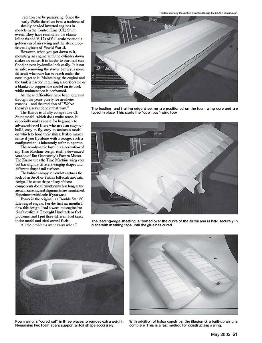
The engine uses stock venturi size, four head shims, and a Sig Radio Control long plug. The fuel tank is a five-ounce Brodak "Old Time Stunt" model made for upright engine airplanes. Fuel normally used is 5% nitromethane Ritches Brew, which has 22% oil—half of it synthetic and half of it castor.
I've used various 13 x 5 and 13 x 6 wood propellers, but the best prop so far is the 12½ x 6½ Bolly three-blade cut to 12 inches and slightly depitched. This gives a comfortable 5.4-second or so lap time at a fast four-stroke setting. The three-blade prop seems to do slightly better at resisting windup in the wind. A four-blade unit might be even better, but I haven't tried it.
About the Name:
Kairos is a Greek word roughly meaning "opportunity." It is used to differentiate two concepts of time: "chronos" is clock, or linear time; "kairos" is time which presents itself in a favorable way. Since the design is a different kind of Time Machine, the name seemed to fit.
Enjoy your Kairos, and always fly safely. MA
Tom Dixon 3390 Woodrun Tr. Marietta GA 30062
Suppliers:
Controline Sales (foam wings, landing gear, Double Star engines) Box 671166 Marietta GA 30066 (770) 973-9238
Model Wings (foam wings) 4112 Devonwood Dr. Marietta GA 30066 (770) 516-0398
Sig Manufacturing Co., Inc. (balsa, hardware, nitrate dope, canopies) 401-7 S. Front St. Montezzuma IA 50171 (800) 247-5008
Brodak Manufacturing (dope, hardware) 100 Park Ave. Carmichaels PA 15320 (724) 966-2726
Transcribed from original scans by AI. Minor OCR errors may remain.