JoeCat
by Joe Beshar
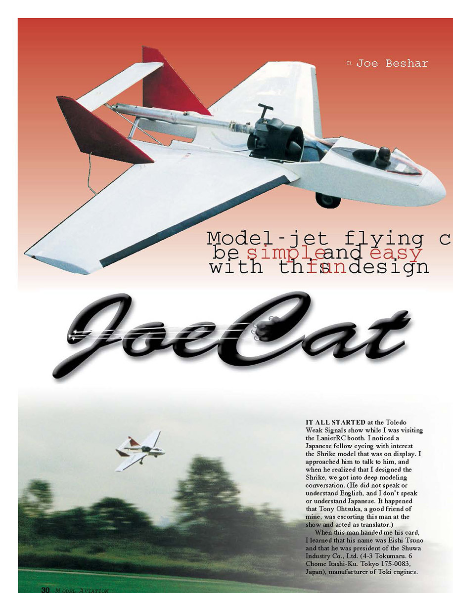
Model-jet flying can be simple and easy with this design
IT ALL STARTED at the Toledo Weak Signals show while I was visiting the Lanier RC booth. I noticed a Japanese fellow eyeing with interest the Shrike model that was on display. I approached him to talk to him, and when he realized that I designed the Shrike, we got into deep modeling conversation. (He did not speak or understand English, and I don't speak or understand Japanese. It happened that Tony Ohtsuka, a good friend of mine, was escorting this man at the show and acted as translator.)
When this man handed me his card, I learned that his name was Eishi Tsuno and that he was president of the Shuwa Industry Co., Ltd. <REDACTED>, manufacturer of Toki engines. Eishi reached into his carrying case and handed me a sample of a .18-cubic-inch engine that the manufacturer makes for model cars. I noticed that the engine had a pull starter, and this sparked my imagination.
The thought came to me that this engine would be desirable because of its small size with a ducted-fan assembly; with its pull-start design, an outside starter with extension would not be required, as is the case with conventional ducted-fan engine and fan assemblies that are available.
I expressed my thoughts to Eishi, and I was surprised when he told me he was working on a prototype unit for just that application. By this time Bubba Spivey, president of LanierRC who was tending the show booth, got into the conversation. It ended when Bubba gave Eishi a kit of the Shrike, compliments of LanierRC, and all departed to continue enjoying the show.
A few weeks later I received a package from Eishi that contained one of the initial DF units complete with engine and tuned pipe. I was delighted, and I proceeded to design a model employing the DF unit when I recognized the opportunity for the challenge.
During the development and testing of the airplane, my modeling teammate Lucas Vallejo came up with the name "JoeCat," and so it was.
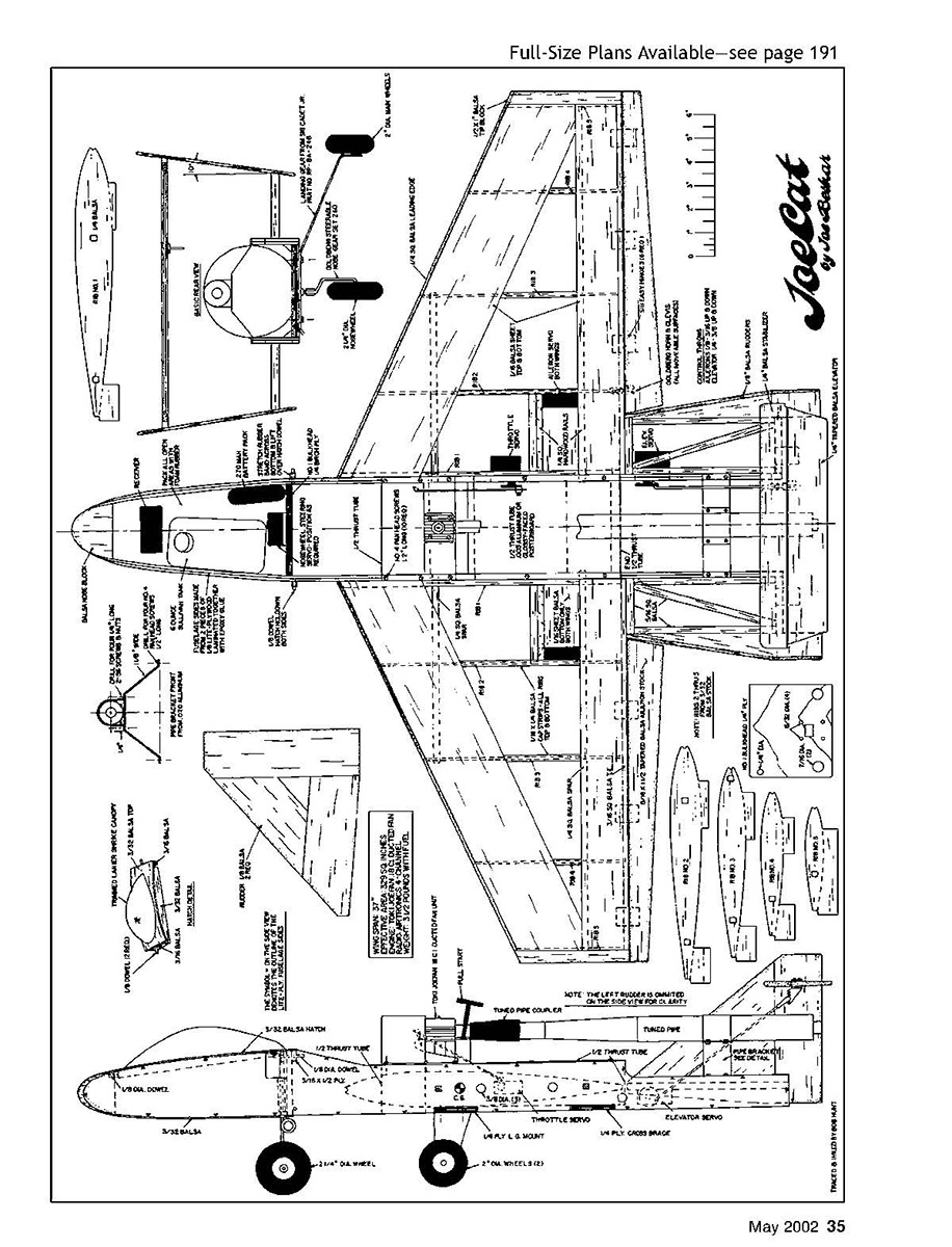
The following outlines the construction details. Referring to the drawing, you will notice the influence of my Shrike design. During the development of the project, some of the more proficient flyers in the area, such as Steve Perlbinder, flew the JoeCat, and all comments regarding its performance were positive.
The initial JoeCat unit was constructed and thoroughly tested and flown using 20%-nitromethane-content fuel—the same used in Radio Control cars. This is the fuel recommended by the manufacturer. A 30%-nitro fuel was tried but showed no advantage.
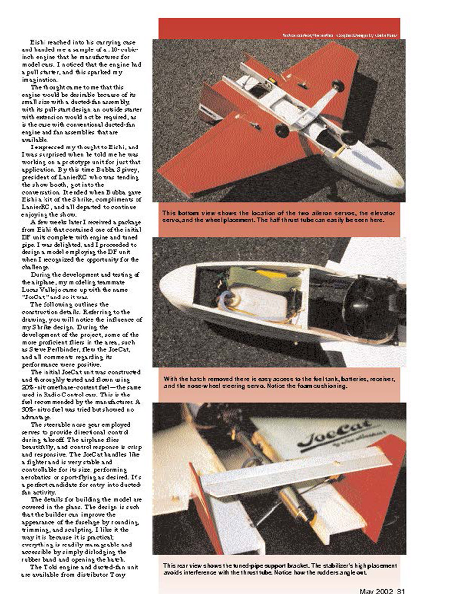
The steerable nose gear employed serves to provide directional control during takeoff. The airplane flies beautifully, and control response is crisp and responsive. The JoeCat handles like a fighter and is very stable and controllable for its size, performing aerobatics or sport-flying as desired. It's a perfect candidate for entry into ducted-fan activity.
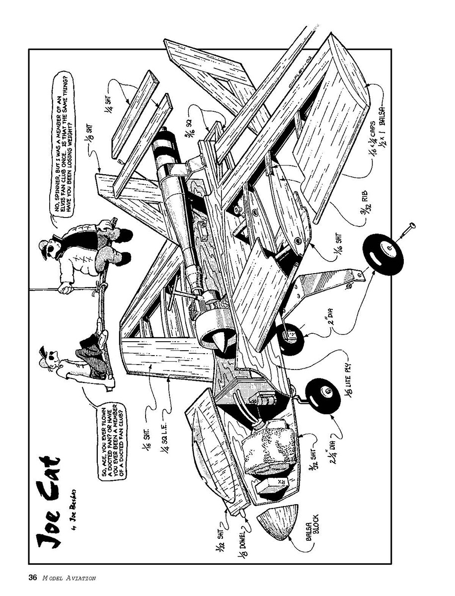
The details for building the model are covered in the plans. The design is such that the builder can improve the appearance of the fuselage by rounding, trimming, and sculpting. I like the way it is because it is practical; everything is readily manageable and accessible by simply dislodging the rubber band and opening the hatch.
The Toki engine and ducted-fan unit are available from distributor Tony Ohsuka <REDACTED>.
Fuselage sides are made from two laminations of 1/8" light plywood. A zip bit is used to open sides for servo-lead passage.
The 1/8"-plywood sides are laminated using carpenter's glue and are clamped with the formers and nose block as shown.
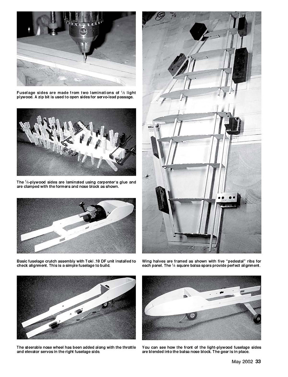
Basic fuselage crutch assembly with Toki .18 DF unit installed to check alignment. This is a simple fuselage to build.
The steerable nose wheel has been added along with the throttle and elevator servos in the right fuselage side.
Wing halves are framed as shown with five "pedestal" ribs for each panel. The 1/4" square balsa spars provide perfect alignment.
You can see how the front of the light-plywood fuselage sides are blended into the balsa nose block. The gear is in place.
Toki DF engine specifications: displacement, 1.08 cubic inch; fan diameter, 92 millimeters (3.62 inches); thrust, 1.1 kilograms (2.42 pounds)—25,000 rpm; and weight, 430 grams (15.17 ounces).
CONSTRUCTION
Fuselage: Cut out the sides as defined by arrow heads from 1/8 light plywood (poplar plywood). Four fuselage sides are required. Make sure that the openings for the elevator and throttle servos are cut in the two sides that will be used to make the right side. (A 1/8-inch-diameter RotoZip® bit mounted in a drill press is ideal for this, and it works well to rout out all the openings.)
Cut out all the plywood bulkhead members and the balsa nose block as shown in the plans. Drill blind-nut holes for the Goldberg steerable front wheel, and cut openings as shown in the bulkhead template. Install blind nuts for the steerable front wheel in the forward bulkhead as dimensioned on the plans.
Apply Elmer's® carpenter's glue to each pair of side bulkheads and the nose block, bend the sides together with bulkheads and nose block over the top view of the plans, and clamp thoroughly and allow glue to set.
Sheet the forward bottom front section, and assemble the removable top front hatch. Drill and install a dowel at the front and rear of the hatch and each bottom side, as shown on the plans, for positioning and rubber-band hold-down.
Drill 3/64-inch-diameter holes for 4 x 1/2 pan-head-screw pilot holes for engine-mounting and installation of half thrust tube under engine mount. Install the throttle and elevator servos as shown on the plans. Adapt a servo arm to the Goldberg Steerable Nose Gear Set #260, and bend as shown.
Wing and Tail Sections: Cut out 10 ribs as outlined. Note that rib 1 is from 1/4 sheet balsa, but the rest are cut from 3/32 sheet balsa. Do not cut off the bottom alignment tabs at this time, but do pencil-mark the cut-off lines for future trimming.
Build wing-panel halves—one right and one left. Slide the ribs onto the 1/4 square balsa spars, in the order shown, and place, pin, and hold squarely on the plans, making sure that spars extend at least 1/2 inch beyond the #1 rib.
Assemble and pin the leading and trailing edges as on the plans, making sure that the entire assembly is fitted and tightly held, then apply cyanoacrylate glue (CyA).
Sand the top of the wing panels lightly. Assemble and glue the leading-and trailing-edge sheeting in place. Repeat this process on the bottom. Install and glue other sheeting as shown on the plans.
Check the servo cavity for fit in the #1 rib. Install and CyA all capstrips. Cut out ailerons as shown on the plans, size and install wingtip blocks, and glue in place.
Size and assemble the extensions to the trailing edge from 5/16 square balsa stock as outlined on the plans. Glue these extensions together and to the wing trailing edge.
The two rudders are made from 1/8 sheet balsa. Cut the pieces for these as shown and glue together. Size the hinging for the mounted stabilizer and elevator, trim and sand as shown, and install hinges.
Final Assembly: Drill pilot holes, and screw in the rear wheel assembly as shown. Install the steerable nose-wheel assembly with the servo connected to the front bulkhead. Be sure to check the 3 3/8-inch dimension at the front wheel and the 3 1/8-inch dimension at the rear wheels for proper incidence angle to the ground.
Fit and glue wings in place, making sure that the thrust cavity is aligned, and install ailerons.
Assemble and glue rudders. Properly position the stabilizer/elevator assembly, and epoxy it in place.
Install and screw in place the Toki DF engine, and assemble the tuned-pipe brackets as shown on the plans with .020-inch-thick x 1 1/8-inch-wide sheet aluminum as detailed.
Cut out the half thrust tube. It can be made from .005-inch-thick aluminum, plastic, or glossy-faced art board. Screw it in place as shown.
Assemble servos in place with control horns and connectors. Install a Sullivan six-ounce slant fuel tank, and complete all plumbing.
Connect all wiring, battery, receiver, servos, etc., and check out operation. Assemble the hatch cover as shown, and install the pilot and the cockpit in place. The canopy is trimmed from the Laine 15 Shrike canopy.
Assemble the entire model for final sanding and finish prep. Finish as desired; the fuselage can be painted, and the wings and open sections are covered with EconoKote®. Apply trim as desired, and your JoeCat is complete and ready for checkout and flight.
For takeoff from a paved runway, open the throttle wide, head the model into the wind, and get set for a new flying experience!
I hope you find the JoeCat as enjoyable as I have. Good luck and happy landings! MA
Joe Beshar <REDACTED> <REDACTED>
JoeCat
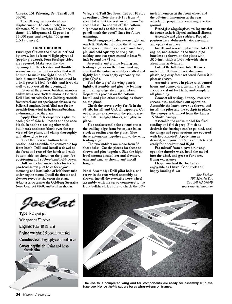
Type: RC sport jet
Wingspan: 37 inches
Engine: Toki .18 DF unit
Flying weight: 3.5 pounds with fuel
Construction: Light plywood and balsa
Covering/finish: Paint and heat-shrink film Full-Size Plans Available—see page 191
Transcribed from original scans by AI. Minor OCR errors may remain.